Latest Power Quality Articles

Apparent Power Calculator
Apparent power calculator for AC circuits computes VA and kVA using RMS voltage, current, and power factor, supporting single-phase and three-phase loads with real power, reactive power, and efficiency insights.
Apparent Power Calculator: Real-World Examples and Uses
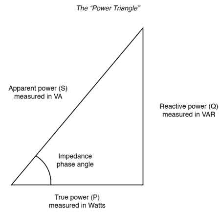
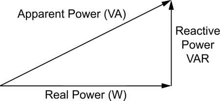
The apparent power calculator estimates total power in an AC circuit using voltage and current. It helps calculate volt-amperes (VA), assess power factor, and compare real, reactive, and apparent power values for designing efficient single-phase and three-phase electrical systems. For a concise overview of definitions and units, see the apparent power guide for additional context.
Power Quality Analysis Training
Power Factor Training
Request…
View more
Sign Up for Electricity Forum’s Power Quality Newsletter
Stay informed with our FREE Power Quality Newsletter — get the latest news, breakthrough technologies, and expert insights, delivered straight to your inbox.
Capacitive Load For Performance and Efficiency
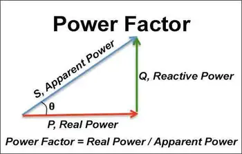
A capacitive load causes current to lead voltage in AC circuits. To calculate power factor, divide real power (kW) by apparent power (kVA). Capacitive loads can correct lagging power factor caused by inductive loads, improving efficiency in electrical systems.
Understanding Capacitive Load: Principles and Applications
A capacitive load primarily comprises capacitors, which temporarily store electrical energy in the form of an electric field. These capacitors have the unique characteristic of leading the voltage in AC circuits, meaning that the current waveform peaks before the voltage waveform. This phenomenon results in a leading power factor, which can impact the…
View more
Real vs Reactive Power Explained
Real vs reactive power refers to the difference between actual usable energy (real power) and energy that oscillates in the system (reactive power). Both are crucial in AC systems for efficient power delivery and voltage regulation.
Real vs. Reactive Power Explained
Real vs reactive power becomes relevant the moment electricians work with motors, transformers, or long feeder runs. These concepts often surface indirectly through low power factor readings, overloaded conductors, nuisance penalties from utilities, or voltage stability issues that are difficult to trace back to a single cause. Confusion usually arises because energy appears to be present and flowing,…
View more
Reactive Power Formula in AC Circuits
Reactive power misjudgment does not merely reduce electrical efficiency. It reshapes transformer sizing, inflates conductor losses, destabilizes voltage profiles, and exposes facilities to avoidable utility penalties. The reactive power formula exists to prevent those outcomes by defining how much system capacity is consumed by energy that sustains electromagnetic fields without producing usable work.
Reactive power (Q) is defined by Q = V × I × sin(θ), where voltage, current, and phase angle determine the magnitude of energy that oscillates between source and reactive elements. This oscillation supports the formation of magnetic and electric fields in motors, transformers, and capacitors, yet…
View more
Reactor Reactance in Power System Explained
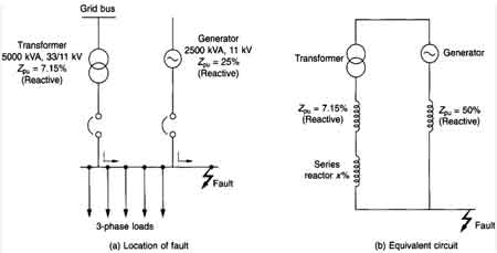
Reactor reactance in power systems controls short-circuit currents, improves voltage stability, and supports grid reliability. By limiting fault current and balancing reactive power, reactors ensure protection, efficient transmission, and system stability.
How Reactor Reactance in Power Systems Works
Introduction to Reactor Reactance
Reactor reactance plays a crucial role in the efficient operation and stability of modern electrical systems. It is a concept deeply rooted in electrical engineering, with significant implications for power quality, voltage regulation, and system protection. Understanding this concept requires exploring how electrical circuits behave and how inductive and capacitive elements shape current flow. Since reactor reactance…
View more
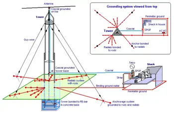
Electrical Grounding Code: How Standards Control Grounding Behavior
Electrical grounding codes define how earthing, bonding, conductors, and electrodes must be installed so fault current follows controlled paths, voltage remains stable, and protective devices operate correctly under NEC, CEC, and IEEE standards.
Electrical Grounding Code: How Standards Control Grounding Behavior
Electrical grounding codes exist to control how electrical systems behave when conditions are no longer normal. They are not written to explain grounding theory or system architecture. They are written to ensure that, when a fault occurs, current flows where it is intended to, and nowhere else.
The NEC, CEC, and IEEE standards define this behavior through conductor…
View more
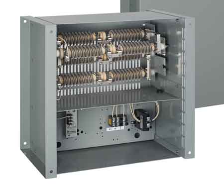
Neutral Grounding Resistor
A neutral grounding resistor limits ground fault current in medium-voltage systems, reducing equipment damage, arc flash risk, and overvoltage stress while preserving system stability and fault detection capability.
Neutral Grounding Resistor in Medium-Voltage Power Systems
A neutral grounding resistor shapes ground fault behavior as part of the broader strategy that establishes system reference and safety, as explained in our formal definition of electrical grounding.
In medium-voltage industrial and utility systems, that control is often the difference between a manageable fault event and a destructive one. A neutral grounding resistor only performs as intended when integrated into grounding system architecture…
View more