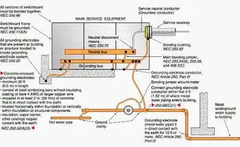
Grounding and Bonding
By William Conklin, Associate Editor
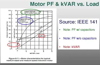
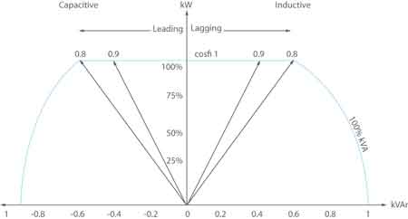
Power Factor Training - Improving System Efficiency
Our customized live online or in‑person group training can be delivered to your staff at your location.
- Live Online
- 6 hours Instructor-led
- Group Training Available
Download Our OSHA 4475 Fact Sheet – Being Aware of Arc Flash Hazards
- Identify root causes of arc flash incidents and contributing conditions
- Apply prevention strategies including LOTO, PPE, and testing protocols
- Understand OSHA requirements for training and equipment maintenance
Grounding and bonding coordinate fault current paths in accordance with NEC Article 250, controlling touch voltage and enabling breakers to trip. Proper coordination protects equipment, supports inspections, and improves electrical safety.
Grounding and Bonding as a Coordinated Safety System
Grounding and bonding operate as a single safety system in electrical installations, even though they are often discussed separately. One establishes a reference to earth. The other ensures conductive parts remain electrically unified. Together, they determine whether a fault clears quickly or lingers long enough to cause damage, injury, or confusion during inspection. For a broader technical foundation, the principles outlined in our electrical grounding overview help clarify how grounding establishes the reference that bonding depends on.
In practice, the distinction matters far less than the coordination. A well-grounded system can still fail if bonding paths are inconsistent. Likewise, perfect bonding cannot compensate for a poorly established grounding reference. The safety outcome depends on how the two work together under fault conditions, not on how neatly they are explained in isolation.
The relationship between grounding and bonding becomes clearer when the core grounding concepts in understanding electrical grounding are understood first.
This page is not intended to redefine grounding theory or restate code tables. Its purpose is narrower and more practical: to examine how grounding and bonding are coordinated in real installations, and why that coordination governs system behavior when conditions depart from normal operation. The coordination discussed here operates within the framework defined in the electrical grounding code, where performance outcomes are prioritized over procedural repetition.
Where Coordination Actually Matters
Most electrical systems perform quietly until something goes wrong. A conductor loosens. Moisture enters a raceway. A piece of equipment develops internal leakage. At that moment, the grounding and bonding system becomes active rather than conceptual.
Sign Up for Electricity Forum’s Power Quality Newsletter
Stay informed with our FREE Power Quality Newsletter — get the latest news, breakthrough technologies, and expert insights, delivered straight to your inbox.
If bonding continuity is poor, fault current may never return to its source. If grounding paths are inconsistent, voltage can appear where it is not expected. Installers often see this first at metal enclosures, conduit joints, or service equipment where continuity depends on small details that drawings rarely capture.
Coordination means that every conductive path, from the service enclosure to the last bonded fitting, participates in the same fault-clearing circuit. When this chain is intact, overcurrent devices behave predictably. When it is not, troubleshooting becomes guesswork. System behaviour under abnormal conditions is easier to interpret when viewed through the lens of a complete grounding system rather than isolated components.
Article 250 as a Framework, Not a Checklist
NEC Article 250 provides the structural logic for grounding and bonding coordination. It does not exist to be memorized section by section. It exists to enforce performance outcomes. Inspection outcomes tend to improve when installers understand how Article 250 principles in the electrical grounding code translate into coordinated field execution.
Those outcomes are simple in principle and demanding in execution:
-
Fault current must have a reliable return path.
-
Touch voltage must remain limited.
-
Protective devices must operate within expected time frames.
-
Conductive parts must not develop independent voltage references.
Article 250 addresses these outcomes through grounding, bonding, and their interaction. When viewed this way, the code reads less like a list of rules and more like a system architecture.
Installers and inspectors who approach grounding and bonding as a unified design problem tend to encounter fewer surprises later.
Bonding as the Fault-Clearing Enabler
Bonding is often described as a shock-prevention measure. In practice, its most critical role is fault-clearing.
Every bonding jumper, bushing, locknut, and connector is part of the same electrical return path. When these connections are inconsistent, fault current disperses instead of concentrating. Breakers may hesitate. Fuses may not respond as expected. The system appears intact, yet remains unsafe. Fault-clearing reliability is strongly influenced by conductor continuity, a relationship explored further in our guide to the grounding electrode conductor.
Bonding succeeds when it is continuous, intentional, and mechanically reliable. It fails when it is assumed.
Service equipment, raceways, enclosures, and structural steel all become part of the bonding network. Coordination means recognizing that none of them operates independently.
Grounding as the Voltage Reference
Grounding establishes system stability. It limits how far voltage can drift during abnormal conditions. It provides a reference point for bonding to equalize around.
Without a stable grounding reference, bonding loses context. Without bonding, grounding loses control.
The two are not interchangeable. They are complementary.
Installations that respect this relationship tend to demonstrate more predictable behavior during transient events, maintenance operations, and system modifications. When grounding and bonding are evaluated as coordinated functions rather than separate tasks, the practical intent behind modern electrical grounding practice becomes more apparent.
Coordination in Separately Derived Systems
Transformers and other separately derived systems reveal coordination problems quickly. Neutral connections, bonding points, and grounding references must be deliberately aligned. When they are not, circulating currents, nuisance tripping, and voltage instability follow.
These are not theoretical concerns. They appear regularly in facilities where grounding and bonding decisions were made in isolation rather than as a coordinated system.
Grounding and Bonding in Inspection Practice
Inspectors rarely evaluate grounding and bonding based solely on theory. They evaluate continuity, termination quality, conductor routing, and physical integrity.
Test Your Knowledge About Power Quality!
Think you know Power Quality? Take our quick, interactive quiz and test your knowledge in minutes.
- Instantly see your results and score
- Identify strengths and areas for improvement
- Challenge yourself on real-world electrical topics
A system that is technically compliant but poorly coordinated often appears inconsistent during inspection. A coordinated system usually appears simple.
The difference lies in how grounding and bonding were treated during design and installation. Differences between U.S. and Canadian grounding practices are examined in detail in our grounding and bonding CSA vs. NEC comparison, which underscores why coordination cannot rely on assumptions.
Coordination Beyond Fault Current
While fault clearing remains the primary safety objective, coordinated grounding and bonding also influence:
-
Equipment noise behavior
-
Surge device effectiveness
-
Transient voltage response
-
Long-term connector reliability
These outcomes are not guaranteed by grounding or bonding individually. They emerge from their interaction.
Grounding and Bonding in Practical Language
Grounding gives the system a reference.
Bonding keeps the system unified.
Coordination makes the system predictable.
That predictability is what allows designers, installers, inspectors, and maintenance personnel to trust the behavior of the system long after installation is complete.
Why Coordination Matters More Than Labels
Grounding and bonding are often taught as separate topics. In the field, they are experienced as a single system.
The installer who understands this distinction builds systems that behave well. The one who does not often build systems that merely comply on paper.
This page exists to reinforce that practical distinction.
Grounding and bonding do not protect people and equipment because they are named correctly. They protect because they are coordinated correctly.
When they are treated as one safety system rather than two checklists, electrical installations become easier to inspect, easier to maintain, and far more predictable when faults occur.
Related Articles

