Real vs Reactive Power Explained
Power Quality Training - Harmonic Analysis, Diagnostics, Mitigation
Our customized live online or in‑person group training can be delivered to your staff at your location.
- Live Online
- 12 hours Instructor-led
- Group Training Available
Download Our OSHA 4475 Fact Sheet – Being Aware of Arc Flash Hazards
- Identify root causes of arc flash incidents and contributing conditions
- Apply prevention strategies including LOTO, PPE, and testing protocols
- Understand OSHA requirements for training and equipment maintenance
Real vs reactive power refers to the difference between actual usable energy (real power) and energy that oscillates in the system (reactive power). Both are crucial in AC systems for efficient power delivery and voltage regulation.
Real vs. Reactive Power Explained
Real vs reactive power becomes relevant the moment electricians work with motors, transformers, or long feeder runs. These concepts often surface indirectly through low power factor readings, overloaded conductors, nuisance penalties from utilities, or voltage stability issues that are difficult to trace back to a single cause. Confusion usually arises because energy appears to be present and flowing, yet not all of it is doing useful work. Understanding how real and reactive power interact clarifies why these problems occur and how AC systems actually behave under load. To better understand how different types of loads affect system efficiency, refer to our overview on capacitive load and how they contrast with resistive and inductive components.
Request a Free Power Quality Training Quotation
When working with AC systems, the key distinction is not whether energy exists, but how it behaves. Real power, measured in watts, is the portion that actually performs work. It turns motors, produces heat, and delivers light. This is the energy that facilities pay for, and equipment relies on to function.
In AC systems, not all electrical energy is used to perform work. Some of it is called reactive power, a component that supports magnetic and electric fields but does not directly drive loads. Because it does no measurable work, it is sometimes called wattless power, yet it remains essential for equipment operation. Devices such as motors and transformers rely on reactive power and inductors to establish the fields they need, which, in turn, generate reactive and apparent power within the system. When combined with real power, these reactive and apparent powers define the total power the source must supply, commonly expressed in volt-amperes VA, even though only part of that energy becomes useful output.
FREE EF Electrical Training Catalog
Download our FREE Electrical Training Catalog and explore a full range of expert-led electrical training courses.

- Live online and in-person courses available
- Real-time instruction with Q&A from industry experts
- Flexible scheduling for your convenience
Reactive power is important because most AC systems are not purely resistive. Inductors and capacitors store energy briefly in magnetic or electric fields, then release it back into the circuit. This exchange does not perform useful work, but it is necessary to sustain voltage and enable motors, transformers, and other inductive equipment to operate. Reactive power is measured in volt-amperes reactive (VAR).
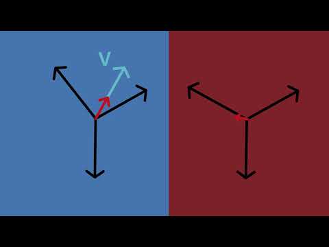
Together, real power and reactive power form apparent power, which represents the total electrical demand placed on a system. In a purely resistive circuit, voltage and current remain in phase, and all supplied energy becomes real power. When inductive or capacitive elements are introduced, the current shifts out of phase with the voltage. The greater this phase shift, the larger the reactive component becomes.
This relationship is central to analyzing AC performance. Phase angle, power factor, conductor sizing, and equipment loading are all consequences of the interaction between real and reactive power. These same principles also influence grounding and bonding strategies, since return paths and fault behavior depend on how current flows through the system.
What Is Reactive Power?
Reactive power (Q) is the portion of AC energy that supports the operation of electrical equipment without directly performing work. It exists because inductors and capacitors must establish magnetic or electric fields before useful energy transfer can occur. This energy continually moves between the source and the load, rising and falling with each AC cycle.
Although reactive power does not register as consumed energy, it has a real impact on system behavior. Excessive reactive demand increases current flow, reduces power factor, and places additional strain on conductors, transformers, and generators. For utilities and industrial facilities alike, managing reactive power is not optional. It directly affects voltage stability, infrastructure costs, and operating efficiency.


Real vs Apparent vs Reactive Power
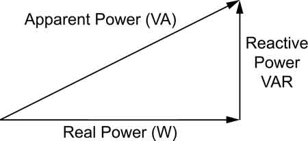
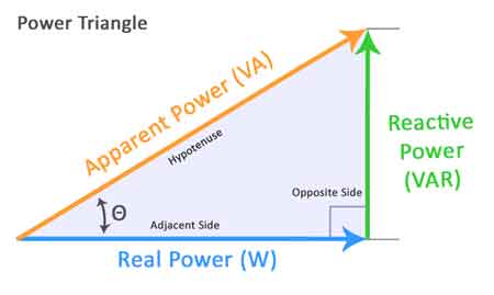
In AC systems, power is not a single quantity but a relationship between three values that describe how energy is supplied, used, and supported. These values are real power, reactive power, and apparent power, and their interaction is commonly illustrated using the power triangle.
Real power represents the work being done. Reactive power represents the energy required to sustain fields within the system. Apparent power reflects the total electrical demand created by both.
This relationship is not abstract. It determines how much current flows, how equipment is rated, and how efficiently energy is delivered. The mathematical relationship between these values is expressed through complex power:
S² = P² + Q²
The phase angle between real and apparent power defines the system power factor. As reactive power increases, that angle widens, efficiency drops, and losses rise.
Comparison of P, Q and S
| Type of Power | Symbol | Unit | Description | Function in AC Systems |
|---|---|---|---|---|
| Real P | P | kW (kilowatts) | The actual energy that performs useful work (e.g., lighting, motors) | Loads measured by wattmeters |
| Reactive P | Q | kVAR (kilovolt-amperes reactive) | Power that sustains electric and magnetic fields but does no useful work | Causes current to circulate; affects PF |
| Apparent P | S | kVA (kilovolt-amperes) | The vector sum of real and Q | Total energy supplied; determines equipment sizing |
| PF | PF | — | Ratio of real power to apparent power (PF = cos?φ) | Indicates efficiency of energy use; should be as close to 1 as possible |
| Phase Angle | φ | Degrees | The angle between voltage and current waveforms | Affects the PF; caused by inductive or capacitive loads |
Practical Examples and Analogies
Understanding real, reactive, and S can be challenging without a tangible frame of reference. One of the most effective analogies is the beer mug analogy, which helps visualize the differences:
Imagine pouring a beer into a glass.
-
The beer itself represents real power (kW)—this is the usable energy that actually does work, such as running a motor or lighting a lamp.
-
The foam that forms on top symbolizes reactive power (kVAR)—it doesn’t do useful work but still takes up space in the system.
-
The total contents of the glass, beer plus foam, represent apparent power (kVA)—the total energy delivered to the system.
Just as only the beer quenches your thirst, only P delivers usable energy. But the foam still occupies part of the glass, just as Q affects the overall capacity and efficiency of an electrical system.
Electricity Today T&D Magazine Subscribe for FREE

- Timely insights from industry experts
- Practical solutions T&D engineers
- Free access to every issue
For electricians, this concept becomes practical when designing or troubleshooting AC systems. For example, a large industrial motor may draw substantial Q, reducing the system’s PF and necessitating the use of capacitor banks to offset the inefficiencies. Understanding the distinction helps ensure proper equipment sizing, voltage regulation, and energy cost control.
Power Factor
Power factor describes how effectively electrical power is converted into useful work. It is defined as the ratio of real power to apparent power and is expressed as the cosine of the phase angle between voltage and current.
A high power factor indicates that most of the supplied energy is being used productively. A low power factor signals that a larger share of the current is supporting reactive elements rather than performing work. This increases system losses, raises utility costs, and forces electrical infrastructure to carry unnecessary current.
In practical terms, improving power factor reduces equipment strain and improves overall power quality. Capacitor banks are commonly used to offset inductive reactive demand, allowing systems to operate closer to their intended efficiency. Discover how to enhance system performance by utilizing power factor correction capacitors, which minimize Q and enhance overall PQ.
Measuring PF
PF is a crucial measure of how effectively electrical energy is being converted into useful work. It is calculated as the cos?φ, or the cosine of the phase angle between current and voltage in an AC circuit. The PF ranges from 0 to 1:
-
A PF of 1 means all energy is being used for work—ideal efficiency.
-
A low PF indicates a higher proportion of Q, resulting in energy waste and the need for larger electrical infrastructure.
Monitoring and improving PF is essential in industrial environments where large inductive loads (like motors) are common. Techniques such as PF correction—typically by installing capacitor banks—can reduce kVAR demand, improve voltage regulation, and minimize utility penalties for inefficient energy use.
Understanding how to measure and correct PF allows electricians to optimize system performance using the principles of the power triangle and complex systems.
Apparent Power (S)
Apparent power represents the total electrical demand placed on an AC system. It combines both real power, which performs work, and reactive power, which sustains system fields. Apparent power determines the current that conductors, transformers, and protective devices must carry, regardless of how much of that energy becomes useful output.
Because equipment is rated in kVA rather than kW, apparent power governs system sizing. Understanding this distinction helps prevent overloaded conductors, undersized transformers, and unnecessary losses.
You can simplify efficiency calculations by using our apparent power calculator to determine the total kVA load in your system.
AC Circuits
Reactive power exists only in AC circuits, where voltage and current alternate direction. This alternating behavior allows inductors and capacitors to store energy during part of each cycle and return it during another. Inductors store energy in magnetic fields, while capacitors store energy in electric fields.
These energy exchanges shift the timing between voltage and current, creating phase displacement. That displacement is the source of reactive power and the reason power factor becomes a critical performance metric in AC systems.
Inductance and Capacitance
Inductance and capacitance are fundamental properties of electrical components that significantly influence AC circuit behaviour. Inductors, like coils and transformers, store energy in magnetic fields, while capacitors store energy in electric fields. When present in an AC circuit, they cause a phase shift between voltage and current, leading to the generation of RP.
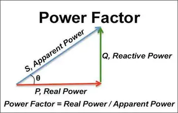
Power Triangle
The triangle visually represents the relationship between real, reactive, and AP in an AC circuit. In this right-angled triangle, P is the adjacent side, RP the opposite side, and S the hypotenuse. The angle between the real and AP is the PF angle. This triangle provides a clear way to understand the interplay between these different forms of electrical energy. Accurate load balancing begins with understanding the basics of three-phase power calculation to ensure efficient energy distribution in industrial systems.
kW and kVAR
P is measured in watts (W) or kilowatts (kW), while P is measured in volt-amperes reactive (VAR) or kilovars (kVAR). These units reflect their distinct nature. It represents the rate of energy consumption and conversion into useful work, while P represents the rate of energy storage and release without performing work.
Power Factor Correction
PF correction improves an electrical system's PF by reducing P. This is typically achieved by adding capacitors to offset the inductive reactance of loads, such as motors and transformers. Improving the PF reduces energy waste, lowers electricity bills, and improves system efficiency. Improving system efficiency and reducing utility charges starts with effective power factor correction to minimize wasted Q.
Efficiency
P is the amount of energy that performs useful work in an electrical system, consumed by loads to produce light, heat, motion, or other desired effects. RP, though necessary for some equipment, doesn't contribute to useful work. Instead, it represents energy stored and released by inductive and capacitive components. Minimizing RP through PF correction improves the overall efficiency of the electrical system. Our article on motor power factor explores how inductive motors affect energy efficiency and how automatic correction devices can help.
Harmonics
Harmonics are distortions in the electrical current waveform that can cause problems. They are multiples of the fundamental frequency of the AC supply, generated by nonlinear loads such as electronic devices and variable-speed drives. Harmonics can increase resistance, leading to a reduced PF and increased energy losses.
Harmonic distortion can severely impact system reliability and efficiency, as explained in our in-depth guide on power quality and harmonics.
Related Articles
