Capacitor Voltage Rating Limitations
By William Conklin, Associate Editor
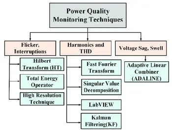
Power Quality Training - Harmonic Analysis, Diagnostics, Mitigation
Our customized live online or in‑person group training can be delivered to your staff at your location.
- Live Online
- 12 hours Instructor-led
- Group Training Available
Download Our OSHA FS3529 Fact Sheet – Lockout/Tagout Safety Procedures
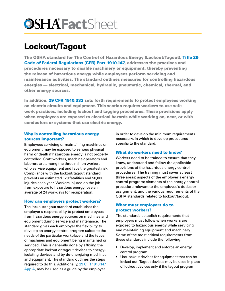
- Learn how to disable machines and isolate energy sources safely
- Follow OSHA guidelines for developing energy control programs
- Protect workers with proper lockout devices and annual inspections
Capacitor voltage rating determines whether a capacitor will survive real operating stress or fail prematurely when voltage spikes, ripple, or waveform distortion exceed its dielectric limits. Engineers rely on this rating not as a suggestion, but as a structural boundary that defines reliability, safety margin, and long-term performance in power electronics and power quality systems.
A capacitor that operates too close to its voltage ceiling may appear stable during commissioning, yet degrade rapidly under transient conditions. This is why voltage rating directly influences component lifespan, thermal behavior, and failure risk. Selecting the correct rating is therefore a design decision, not a catalog lookup.
Capacitor voltage rating expresses the maximum continuous electrical stress the dielectric can tolerate without breakdown. In real installations, designers deliberately choose ratings above the nominal system voltage to account for ripple, harmonics, switching noise, and surge events that are not shown in schematic diagrams. The rating is not about normal operation. It is about survival when conditions stop being ideal.
Capacitor Voltage Rating Fundamentals
Voltage rating defines the dielectric strength of a capacitor under sustained electrical stress. Once that threshold is exceeded, insulation damage accelerates, internal heating rises, and failure probability increases. Because real circuits rarely maintain perfectly stable voltage, responsible designs treat the printed rating as a minimum boundary rather than a target operating point.
This is why derating is standard practice in professional power quality and electronics design. Voltage margin is not added for comfort. It is added to protect against unpredictable operating behavior that cannot be eliminated in real systems.
Electricity Today T&D Magazine Subscribe for FREE

- Timely insights from industry experts
- Practical solutions T&D engineers
- Free access to every issue
AC vs DC Capacitor Voltage Rating
AC and DC voltage ratings are not interchangeable because alternating polarity places greater dielectric stress on the capacitor material. Each reversal forces the dielectric to realign its internal charge structure, increasing heating and molecular fatigue. As a result, a capacitor rated at 100 V DC will often carry a much lower AC voltage rating.
This distinction becomes critical in applications such as motor circuits, power factor correction equipment, and waveform-distorted environments. In these systems, misinterpreting AC versus DC ratings directly leads to shortened service life and unexpected failures.
To understand how voltage behavior affects power delivery, visit apparent power in AC circuits or explore apparent power vs real power.
Dielectric Material and Performance
The dielectric is at the heart of every capacitor, and its composition shapes the part’s stability, tolerance, and life expectancy. C0G (NPO) materials remain stable over temperature and voltage swings, which is ideal for precision circuits. X7R devices offer higher capacitance in small packages but exhibit greater load-dependent variation. Z5U and Y5V types are cost-efficient but tend to drift significantly with changes in temperature or voltage. Choosing the right material is not an academic exercise. In power factor correction banks, snubber circuits, and other high-stress environments, dielectric behaviour influences long-term performance more than the label's nominal rating.
Component behavior is not solely based on nameplate ratings; it depends on where and how it’s used. In sensitive circuits, such as those involving power factor correction, dielectric selection is key. Learn more in our guide to capacitor banks and power factor.
Frequency and Heat Considerations
High frequency does more than raise current; it adds heating inside the part, and that heating chips away at the effective voltage limit. At the same time, ambient temperature affects how well the dielectric resists breakdown. As conditions grow hotter, the safe operating margin narrows. Engineers compensate by derating, selecting a higher stated voltage than the circuit technically requires. This approach provides insurance against heat rise, fast switching edges, and environmental extremes. To better understand how surges affect performance, visit our resource on inrush surge current.
Safety Margins and Proper Derating
No capacitor should be operated at its exact nameplate value. A margin of 1.5 to 2 times the expected working voltage is standard practice, especially when the circuit experiences transients or fluctuating loads. This extra headroom smooths out the impact of spikes and aging. Renewable energy inverters, industrial controls, and power automation gear all benefit from derated components because they endure constant electrical and thermal stress.
If you're unsure how component values relate to total load, refer to the apparent power formula, or use a calculator for power factor to balance reactive and real components in your design.
Choosing Ceramic Components
Ceramic capacitors remain popular due to their compact size and predictable high-frequency behavior. Even so, they vary widely in their responses to temperature, polarity, and applied voltage. Class 1 ceramics, like C0G, offer the greatest stability, while Class 2 and Class 3 parts trade stability for higher capacitance density. Matching the ceramic type to the operating environment and waveform ensures the component behaves as expected over the system’s life. Poor selection can lead to drifting capacitance, reduced voltage tolerance, or, in extreme cases, catastrophic failure. Learn how these devices affect system efficiency in our article on capacitive loads.
Frequently Asked Questions
What does it mean, and why is it important?
It represents the highest voltage the part can tolerate without breaking down. Operating above that level risks overheating, dielectric failure, or circuit damage.
How is the correct capacitor voltage rating selected?
Designers multiply the circuit’s maximum voltage by a safety factor, typically 1.5-2, to account for spikes, ripple, and aging.
What happens if the capacitor voltage rating is overrated?
Using a component with a higher rating is safe. The only tradeoffs are cost and physical size.
FREE EF Electrical Training Catalog
Download our FREE Electrical Training Catalog and explore a full range of expert-led electrical training courses.

- Live online and in-person courses available
- Real-time instruction with Q&A from industry experts
- Flexible scheduling for your convenience
Can a higher-rated part be used safely?
Yes. Most technicians prefer using a higher-rated part when space allows because it offers greater durability.
How does temperature impact voltage limits?
Rising temperatures reduce dielectric strength and increase the risk of failure, which is why derating is recommended in warm environments.
Selecting the correct capacitor voltage rating strengthens the entire system. By carefully considering AC versus DC limits, dielectric characteristics, heat, frequency, and safety margins, you build circuits that remain stable, safe, and dependable over years of operation.
Related Articles
• Apparent Power vs Real Power
