Power Factor Calculation
By R.W. Hurst, Editor
Power Factor Training - Improving System Efficiency
Our customized live online or in‑person group training can be delivered to your staff at your location.
- Live Online
- 6 hours Instructor-led
- Group Training Available
Download Our OSHA 3875 Fact Sheet – Electrical PPE for Power Industry Workers

- Follow rules for rubber gloves, arc-rated PPE, and inspection procedures
- Learn employer obligations for testing, certification, and training
- Protect workers from arc flash and electrical shock injuries
Power factor calculation determines how efficiently an electrical system converts supplied power into useful work by comparing real power to apparent power under operating load conditions. It reveals reactive losses, current waste, and how much of the incoming energy actually produces output.
When power factor is misunderstood or ignored, systems quietly run hotter, transformers and conductors are loaded beyond their nameplate ratings, and utility penalties increase even when total kW demand appears unchanged. Poor power factor does not usually cause immediate failure, but it steadily reduces capacity, shortens equipment life, and masks the true cause of voltage instability and nuisance tripping.
Power factor calculation matters because it influences design and operational decisions that cannot be corrected later without cost. It affects conductor sizing, transformer selection, capacitor placement, VFD integration, and even how facilities negotiate demand charges with utilities. Without an accurate understanding of power factor behavior under load, engineers and technicians often treat symptoms rather than the electrical condition that created them.
Real power divided by apparent power defines the power factor formula, reflecting how voltage and current alignment impact efficiency; for the canonical mathematical expression, see the detailed formula page.
Power Factor Calculation: How Electrical Efficiency Is Measured
Power factor calculation is a practical diagnostic method used throughout the electrical industry to evaluate how efficiently energy is used in a circuit. By examining the relationship between watts, volt-amperes, and current, it becomes possible to see where capacity is being consumed without producing useful work.
In AC systems dominated by motors and inductive equipment, reactive effects cause current to rise while real output remains unchanged. This produces a lagging power factor condition in which conductors, breakers, and transformers must carry extra current that contributes nothing to productive power. Because power factor reflects the ratio of active power to apparent power, even small shifts in reactive loading can significantly affect overall system performance.
FREE EF Electrical Training Catalog
Download our FREE Electrical Training Catalog and explore a full range of expert-led electrical training courses.

- Live online and in-person courses available
- Real-time instruction with Q&A from industry experts
- Flexible scheduling for your convenience
In facilities filled with motors, transformers, VFDs, and electronic power supplies, power factor calculation explains problems that only appear under real operating conditions. It exposes why components overheat, why capacity disappears faster than expected, and why electrical systems feel overloaded long before kW limits are reached.
Improving PF is ultimately about improving power quality, trimming unnecessary losses, and ensuring that electrical systems operate as cleanly and efficiently as possible.
Power Quality Analysis Training
Request a Free Power Quality Training Quotation
Definition and Range of Power Factor
For calculation purposes, power factor is expressed as the ratio of real power (kW) to apparent power (kVA). Because measured apparent power is always equal to or greater than the real power delivered, PF values recorded in the field always fall between 0 and 1.
A value near 1 suggests that very little extra current is circulating. Lower values indicate that more current is tied up supporting electric or magnetic fields rather than doing work. PF calculations help determine whether equipment is being supplied efficiently, whether reactive effects are placing strain on conductors, and whether the system behaves as intended when loaded.
Different types of equipment influence these calculations. Resistive heaters produce PF values close to unity; motors typically exhibit lagging PF, and electronic devices may introduce waveform distortion that affects true PF readings. These distinctions directly affect the numbers a technician sees during measurement.
Types of Loads and Their Effect on PF
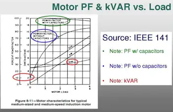
Power factor calculation becomes most useful when the facility’s real load characteristics are considered. Motors draw magnetizing current, VFDs inject harmonics, and lighting systems can introduce non-linear currents. PF values often shift throughout the day as equipment cycles on and off.


Performing PF calculations at several load points, light, nominal, and peak, gives operators a clearer picture of how close circuits are to their practical limits. For example, a lightly loaded induction motor can show a low PF that improves as it approaches its rated output. A building filled with electronic equipment might produce acceptable displacement PF yet suffer from poor true PF due to waveform distortion.
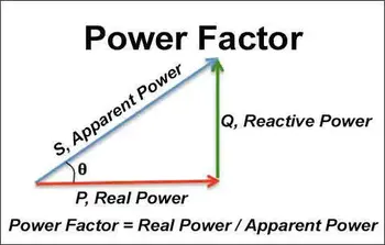
The Power Triangle
The power triangle provides a useful structure for interpreting PF calculations. Real power (P) lies on the horizontal axis, reactive power (Q) rises vertically, and apparent power (S) forms the diagonal. Once two values are measured, the third can be calculated.
The angle between P and S reflects how far voltage and current have drifted from alignment. PF can then be obtained from the measured angle or by dividing P by S. This approach allows technicians to evaluate PF using real data from test instruments rather than relying on assumptions.
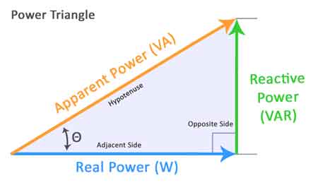
Power Triangle Diagram – Visual representation of the relationship between P, Q, and S in AC circuits, showing how PF is calculated using the phase angle (φ).
Example Calculation
Consider a system delivering 5 kW of real power while drawing 6 kVA of apparent power:
PF = 5 ÷ 6 = 0.83
A value like this indicates that the installation requires more current than a purely real load. That extra current builds heat in cables, increases transformer loading, and may reduce available capacity upstream. When technicians repeat calculations under different operating scenarios, patterns emerge that help diagnose equipment stress or supply inefficiencies.
Since apparent power plays a central role in PF calculation, referencing an apparent power calculator or using the apparent power formula helps ensure accuracy.
Test Your Knowledge About Power Quality!
Think you know Power Quality? Take our quick, interactive quiz and test your knowledge in minutes.
- Instantly see your results and score
- Identify strengths and areas for improvement
- Challenge yourself on real-world electrical topics
Accurate PF results also depend on reliable apparent power measurements, especially in systems with fluctuating loads.
Since PF is calculated using the apparent power formula, it is essential for accurate results.
Load Factor vs. PF
Load factor and power factor both influence electrical performance, but they measure different things. PF is the instantaneous ratio of real to apparent power. Load factor, however, compares average consumption over time to peak demand levels.
A facility may exhibit excellent PF during heavy operations yet still run inefficiently if its load factor is low. Conversely, a high load factor combined with low PF points to continuous reactive waste. Looking at both metrics together provides a more complete picture of system behavior and improvement opportunities.
Power Factor Correction (PFC)
When calculations reveal that PF is below acceptable levels, correction becomes a practical step. Capacitors remain the most common option because they counteract inductive effects and supply leading reactive current locally. This reduces the reactive current the utility must provide.
The required capacitance depends on the voltage, frequency, and the amount of reactive current to be offset. A basic sizing expression,
C = Q / (2πfV²),
gives a useful starting point for small or stable loads. Larger facilities often repeat PF calculations under different operating conditions to refine capacitor sizing and verify that corrective equipment is performing as expected.
Advanced Correction Methods
Some installations require more adaptive approaches. Switched capacitor banks accommodate varying loads. Synchronous condensers provide mechanical adjustability. STATCOMs and active harmonic filters address both displacement PF and harmonic distortion, both of which are increasingly important in environments dominated by electronic drives and power supplies.
PF calculations before and after installation confirm whether the chosen corrective approach improves voltage stability, reduces equipment heating, and lowers upstream demand.
For step-by-step guidance, our how to calculate power factor page provides practical examples and explains how to use a power factor calculator.
Distortion PF and Harmonics
Modern electrical systems often show differences between displacement PF and true PF due to harmonic distortion. Electronic devices deform the current waveform, lowering true PF even when traditional PF appears acceptable.
True PF is calculated using the expression:
True PF = Displacement PF ÷ √(1 + THDi²)
Technicians use this calculation to diagnose overheating, nuisance tripping, or unexplained device failures. Harmonic filters or corrective equipment are then selected based on measured distortion levels.
Accurate PF calculation helps facilities reduce losses, stabilize voltage, extend equipment life, and avoid penalties. By combining displacement PF, true PF, load factor, and harmonic analysis, maintenance and design teams gain a complete understanding of electrical performance and can make informed decisions about upgrades and improvements.
Frequently Asked Questions
How do you calculate the PF?
Divide real power (in watts) by apparent power (in volt-amperes). This numerical value shows how effectively energy is being used. When inductive loads dominate, additional current flows, and PF calculations usually reflect that drop in efficiency. Improving PF often involves installing a power factor correction capacitor as part of a broader power factor correction strategy.
How are PF and load factor calculated?
PF is determined from real and apparent power. Load factor compares average use over time to peak demand. Together, the two calculations show how efficiently the electrical infrastructure operates both moment-to-moment and over the long term. For motor-driven systems, our motor power factor guide explains the specific challenges and solutions for improving PF in industrial applications.
What is 0.9 power factor?
A calculated PF of 0.9 means that most of the supplied energy is converted to useful work, while a smaller portion circulates as reactive current. Many utilities encourage PF values at or above this level to maintain system efficiency. Harmonic distortion can reduce true PF, so learning about power quality and harmonics, and using a power quality analyzer, can help maintain system efficiency.
Related Pages
