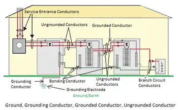
Grounding and Bonding NEC Installations
By Frank Baker, Technical Editor
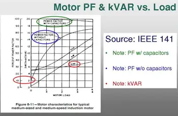
Power Factor Training - Improving System Efficiency
Our customized live online or in‑person group training can be delivered to your staff at your location.
- Live Online
- 6 hours Instructor-led
- Group Training Available
Download Our OSHA 3875 Fact Sheet – Electrical PPE for Power Industry Workers
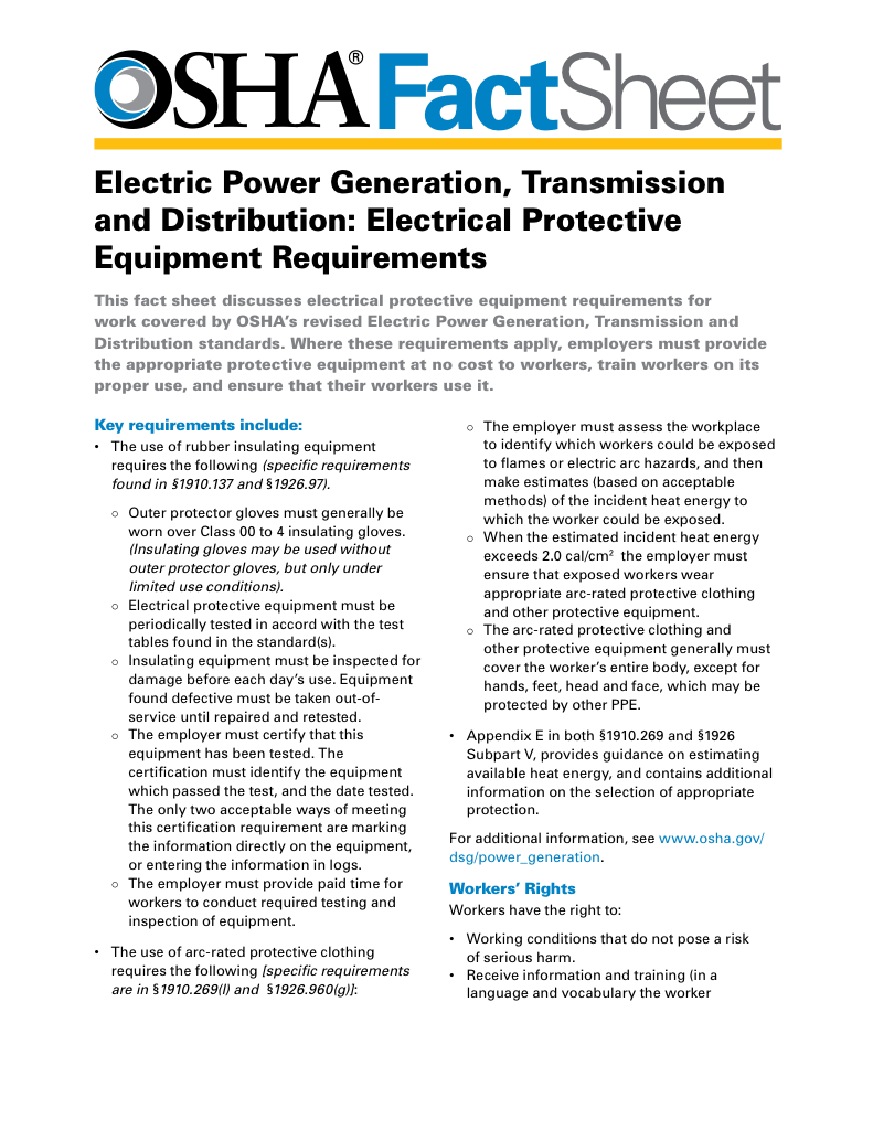
- Follow rules for rubber gloves, arc-rated PPE, and inspection procedures
- Learn employer obligations for testing, certification, and training
- Protect workers from arc flash and electrical shock injuries
Grounding and bonding NEC installations rely on coordinated fault paths and stable references. This guide shows how NEC intent becomes safer service equipment, raceways, and enclosures.
Why Grounding and Bonding NEC Matters
Grounding and bonding NEC installations depend less on memorized rules than on understanding how fault current is expected to move through a system. The National Electrical Code does not treat grounding and bonding as parallel checklists. It treats them as a coordinated safety architecture that determines whether protective devices operate correctly and whether exposed metal remains safe to touch.
In practice, many NEC grounding problems arise not from missing conductors but from misunderstanding how those conductors are meant to function together.
This page focuses on how grounding and bonding are applied under NEC intent in real installations. It does not restate grounding theory. It does not summarize Article 250. It explains how NEC grounding and bonding decisions affect system behavior in service equipment, raceways, enclosures, and derived systems. Canadian and U.S. bonding rules only make sense when interpreted within the broader framework of electrical grounding.
NEC Intent Before NEC Sections
NEC Article 250 is often approached as a collection of rules. In the field, it behaves more like a performance system.
The NEC expects:
• A predictable fault-current return path
• Limited touch voltage during abnormal conditions
• Continuous bonding between conductive parts
• A stable system reference
When these outcomes are achieved, compliance follows naturally. When they are not, installations may pass inspection yet still behave unpredictably during faults.
Grounding and bonding NEC installations succeed when designers and electricians read Article 250 as a system description rather than a checklist.
FREE EF Electrical Training Catalog
Download our FREE Electrical Training Catalog and explore a full range of expert-led electrical training courses.

- Live online and in-person courses available
- Real-time instruction with Q&A from industry experts
- Flexible scheduling for your convenience
Fault Current Is the Design Driver
The NEC does not ground equipment for convenience. It grounds equipment so that fault current has a deliberate path back to its source.
Bonding establishes that path.
Grounding stabilizes the reference.
When either is interrupted, fault current disperses. Breakers hesitate. Metal parts rise in voltage. The system appears intact while operating in a degraded safety state. This behavior is often first observed at grounding electrodes, which form the physical foundation of the fault-current return path in NEC systems, as explained in grounding electrodes.
NEC grounding and bonding are therefore not primarily about earth. They are about circuit completion.
Bonding Under NEC Installations
Bonding is the silent workhorse of NEC grounding systems.
Every enclosure, raceway, connector, and jumper either strengthens or weakens the fault-clearing circuit. Loose fittings, painted joints, or assumed continuity are often where NEC intent breaks down in practice.
Bonding under NEC installations succeeds when it is:
• Mechanically reliable
• Electrically continuous
• Intentionally routed
It fails when it is assumed. In medium-voltage and industrial systems, bonding effectiveness is closely tied to the application of neutral grounding resistors, as described in neutral grounding resistor installations.
Grounding as a System Reference
Grounding under NEC establishes the system reference point that bonding equalizes around.
Without that reference, voltage has no anchor.
Without bonding, the reference has no reach.
The NEC treats grounding and bonding as complementary functions because neither can perform its role in isolation. This relationship becomes especially clear when grounding is applied to rotating machines such as generators, as outlined in grounding a generator.
NEC Challenges in Derived Systems
Separately derived systems reveal grounding and bonding errors quickly.
Transformer secondaries, generators, and alternate power sources all require deliberate grounding and bonding decisions. When those decisions are copied from unrelated installations, circulating currents, nuisance tripping, and unstable voltages often follow, particularly in systems that rely on proper transformer grounding design.

NEC grounding and bonding installations must be interpreted in the context of each system configuration, not transferred mechanically from one project to the next.
Inspection Reality
Inspectors rarely judge NEC grounding and bonding by theoretical explanations. They judge it by continuity, termination quality, conductor routing, and physical integrity.
A well-coordinated NEC grounding system looks simple.
A poorly coordinated one looks complicated.
The difference is not in the code. It is in how the code was understood. This contrast becomes especially visible in large facilities where substation grounding must integrate multiple grounding paths into a single reference system.
NEC Installations Beyond Fault Clearing
While fault clearing remains the primary NEC objective, grounding and bonding also influence:
• Surge device behavior
• EMI susceptibility
• Control system stability
• Long-term connector reliability
These outcomes are not controlled by grounding or bonding alone. They emerge from how the two are coordinated, particularly in safety-critical environments where electrical safety grounding governs both shock protection and arc-flash risk.
Practical Language for NEC Grounding and Bonding
Grounding provides the reference.
Bonding completes the circuit.
Coordination makes the system predictable.
That predictability is what allows NEC installations to remain safe long after the drawings are forgotten.
The NEC Perspective
The NEC does not ask whether grounding and bonding are merely present. It asks whether they function together as a coordinated system.
It asks whether they work together.
When they do, systems behave.
When they do not, systems only appear compliant.
Grounding and bonding NEC installations succeed when intent is understood before conductors are installed.
The code does not protect people because it is written correctly.
It protects people when its principles are applied correctly.
Sign Up for Electricity Forum’s Power Quality Newsletter
Stay informed with our FREE Power Quality Newsletter — get the latest news, breakthrough technologies, and expert insights, delivered straight to your inbox.
Grounding provides the reference.
Bonding gives that reference meaning.
Together, they define how NEC installations remain safe, predictable, and electrically honest.
Related Articles
