NEC 250.122 Explained
Power Factor Training - Improving System Efficiency
Our customized live online or in‑person group training can be delivered to your staff at your location.
- Live Online
- 6 hours Instructor-led
- Group Training Available
Download Our OSHA 3875 Fact Sheet – Electrical PPE for Power Industry Workers
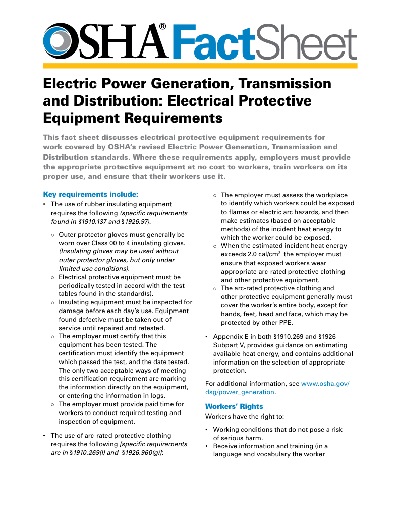
- Follow rules for rubber gloves, arc-rated PPE, and inspection procedures
- Learn employer obligations for testing, certification, and training
- Protect workers from arc flash and electrical shock injuries
NEC 250.122 sets minimum equipment grounding conductor sizes based on overcurrent device ratings, helping safely clear fault current, limit overheating, and reduce shock and fire risk in residential, commercial, and industrial electrical systems.
The Importance of NEC 250.122 in Electrical Safety
Grounding failures rarely look dramatic at first. More often, they show up as nuisance trips, odd equipment behavior, or a breaker that does not clear a fault as cleanly as it should. NEC 250.122 applies when the system is under stress, not when everything is running normally. The goal is simple: ensure the equipment grounding conductor can carry fault current long enough and reliably enough for the protective device to operate.
This section also matters to overall system performance, even if it is not written as a “power quality” rule. A proper fault-clearing path reduces the chance of sustained arcing, overheated raceways, damaged insulation, and energized metal parts that should never be energized. When people treat the EGC as secondary to the phase conductors, that is when the risk starts to climb.
Grounding and Bonding and the NEC 250 Training
Electrical Grounding and the CE Code Training
Request a Free Power Quality Training Quotation
Understanding NEC 250.122: Equipment Grounding Conductor Sizing
The National Electric Code (NEC), specifically NEC 250.122, ties the minimum equipment grounding conductor size to the overcurrent protective device's ampere rating. That is the key relationship, and it is deliberately conservative. The Code is not asking whether the grounding conductor can “usually” handle what might happen. It assumes a fault, high stress, and that the grounding path will hold together electrically and mechanically.
In practical terms, the equipment grounding conductor is part of the fault-clearing circuit. It is not there for normal load current, and it is not a cosmetic add-on. During a fault, it provides a low-impedance return path back to the source so the protective device sees enough current to open quickly. If the EGC is too small, damaged, or poorly terminated, the fault can linger, heat can build, and exposed conductive parts can remain at dangerous potential.
FREE EF Electrical Training Catalog
Download our FREE Electrical Training Catalog and explore a full range of expert-led electrical training courses.

- Live online and in-person courses available
- Real-time instruction with Q&A from industry experts
- Flexible scheduling for your convenience
NEC Table 250.122 – Quick Reference
| Overcurrent Device Rating (Amps) | Minimum Copper EGC Size (AWG or kcmil) |
|---|---|
| 15–20 | 14–12 |
| 60 | 10 |
| 100 | 8 |
| 200 | 6 |
| 400 | 3 |
| 800 | 1/0 |
| 1200 | 3/0 |
This quick reference is a starting point. In the field, trouble-causing situations usually involve upsized conductors, shared raceways, motor circuits, and parallel runs. That is where the subsections matter.
Subsection Highlights: 250.122(B), (C), (D), and (F)
In addition to the base rule in 250.122 (A), several key subsections affect grounding conductor sizing in real-world installations:
250.122(B) – Upsizing for Larger Conductors
This is the one that gets missed on long feeders. If you increase the size of ungrounded conductors for voltage drop or design reasons, the EGC must be increased proportionally in circular mil area. The intent is to keep the fault path's scaling in step with the circuit it is meant to protect. It is not about efficiency; it is about fault-clearing integrity.
250.122(C) – Multiple Circuits in One Raceway or Cable Tray
If multiple circuits share the same raceway or tray, the Code permits a single EGC, provided it is sized for the largest overcurrent device protecting those circuits. That matches how fault current behaves in the real world; it will take the best available return path, not the one a drawing implies.
250.122(D) – Motor Circuits
For motors, the EGC size is based on the branch-circuit protective device, not the motor’s full-load current. This distinction matters because motor protection often reflects starting conditions and equipment realities, not just nameplate numbers. The grounding conductor has to be sized for the device that will clear the fault.
250.122(F) – Parallel Conductors
When conductors are run in parallel, a separate EGC is required in each parallel run, and each must be sized per the table. This prevents uneven sharing and avoids the situation where one grounding path carries more than it should during a fault event.
Sample Calculation: Upsizing and Proportional EGC Sizing
Scenario – A feeder is protected by a 200A circuit breaker and normally would use 3/0 copper conductors. Due to voltage drop over a long run, the conductors are upsized to 350 kcmil.
Step 1 – Base EGC size from NEC Table 250.122
For 200A, the required copper EGC is 6 AWG (26,240 circular mils).
Step 2 – Upsizing ratio
3/0 AWG = 167,800 cmil
350 kcmil = 350,000 cmil
Ratio = 350,000 / 167,800 ≈ 2.09
Step 3 – Multiply EGC size by same ratio
6 AWG = 26,240 cmil
26,240 × 2.09 ≈ 54,841 cmil
Closest standard conductor: 4 AWG (62,420 cmil)
Result – Use 4 AWG copper as the upsized EGC to remain compliant.
Qualified Person Exception
NEC Article 100 defines a qualified person as someone with the skills and knowledge related to the construction and operation of electrical equipment, along with safety training to recognize and avoid hazards. In practice, this is less about formal titles and more about demonstrated competence. On many projects, that responsibility falls to a licensed electrical engineer or a master electrician acting within a clear scope and authority.
The 2020 and 2023 NEC introduced an exception to 250.122(B) that reflects this professional judgment. When ungrounded conductors are increased in size solely to address voltage drop, a qualified person may size the equipment grounding conductor without proportional upsizing. This allowance recognizes that experienced professionals can evaluate fault behavior and system performance beyond simple table-based scaling.
That discretion is not automatic. If the equipment grounding conductor is not upsized, the decision must be defensible and supported by documentation, calculations, or design authority. The intent is not convenience, but accountability for the installation's fault-clearing performance.
Frequently Asked Questions
What does 250.122 cover in terms of equipment grounding conductor sizing?
It sets minimum EGC sizes based on the rating of the overcurrent protective device. Table 250.122 is the core reference, but the subsections address common real-world conditions such as conductor upsizing, shared raceways, motors, and parallel runs.
Electricity Today T&D Magazine Subscribe for FREE

- Timely insights from industry experts
- Practical solutions T&D engineers
- Free access to every issue
How do I calculate the correct size for an equipment grounding conductor?
Start with the overcurrent device rating and use Table 250.122. Then check whether any conditions force adjustments, especially 250.122(B) when ungrounded conductors are increased in size for voltage drop or design reasons. If you are in a motor application or have parallel conductors, the applicable subsection will often drive the final decision. When upsizing for long runs or voltage drop, the apparent power and load characteristics may also affect EGC sizing.
What happens if the equipment grounding conductor is undersized?
During a fault, the conductor may overheat or fail to provide a low-impedance return path. That can delay or prevent the protective device from operating as intended, increasing shock risk, increasing the chance of sustained arcing, and increasing damage to equipment and insulation systems. This makes proper grounding system design essential. Compliance with the standard also helps ensure systems pass inspection and avoid costly rewiring. It complements other grounding and bonding standards and includes guidelines for both new installations and for increasing the conductor size due to specific conditions.
Does 250.122 apply to both residential and commercial installations?
Yes, the standard applies to both residential and commercial installations. Whether for a single-family home, a neutral grounding resistor in an industrial facility, or a ground grid in a commercial building, the same principles of EGC sizing apply.
How do adjustments for voltage drop affect equipment grounding conductor sizing?
When ungrounded conductors are increased for voltage drop, 250.122(B) typically requires proportional upsizing of the EGC in circular mil area. The 2020 and 2023 NEC exceptions allow a qualified person to size the EGC without proportional upsizing when the only reason for increasing the conductor size is voltage drop. Still, such a decision requires clear authority and defensible engineering judgment.
NEC 250.122 is one of those Code rules that looks simple until you start applying it to real installations. The table gives the minimum, but the subsections keep the grounding path aligned with the way systems are actually built. If you size the EGC thoughtfully, faults clear faster, equipment takes less abuse, and exposed metal is less likely to become a surprise hazard. Use how to check if an area is grounded to verify effectiveness in the field.