Grounding System - Electrical Fault Protection
By R.W. Hurst, Editor
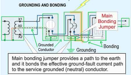
Grounding and Bonding and The NEC - Section 250
Our customized live online or in‑person group training can be delivered to your staff at your location.
- Live Online
- 12 hours Instructor-led
- Group Training Available
Download Our OSHA FS3529 Fact Sheet – Lockout/Tagout Safety Procedures
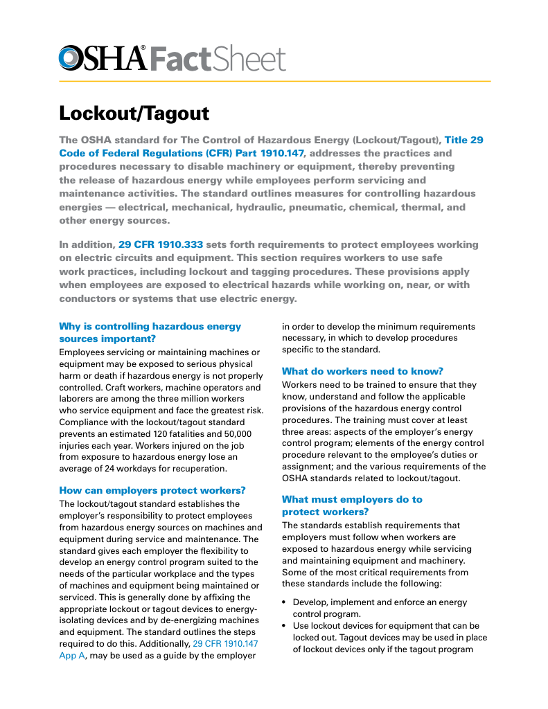
- Learn how to disable machines and isolate energy sources safely
- Follow OSHA guidelines for developing energy control programs
- Protect workers with proper lockout devices and annual inspections
The electrical grounding system is the physical and electrical arrangement of conductors, electrodes, and bonding paths that allows grounding to function as intended.
Grounding System Design in Electrical Power Networks
A grounding system is not a single conductor or a single rod in the soil. It is a coordinated structure that allows an electrical system to behave predictably when conditions are no longer normal. Its purpose is not only to provide a connection to earth but also to organize how voltage references, bonding, and fault pathways interact across the entire installation. The regulatory rules governing the application of grounding conductors, electrodes, and bonding connections are defined in the electrical grounding code standards.
When a grounding system is properly designed, faults do not disappear. They become manageable. Voltage remains controlled, protective devices remain coordinated, and exposed metal parts remain near the same electrical potential.
That predictability is the real value of system grounding.
In a properly designed grounding system, conductors and bonding paths ensure that fault energy is guided back toward its reference point through predictable electrical routes, rather than through equipment frames or people.
A grounding system is easier to interpret when its purpose is viewed through the foundational concepts introduced in our conceptual overview of grounding behavior.
Grounding and Bonding and the NEC 250 Training
Electrical Grounding and the CE Code Training
Request a Free Power Quality Training Quotation
What a grounding system actually controls
Every electrical system needs a stable reference point. Without it, voltage has no reliable meaning and fault behavior becomes unstable. The grounding system establishes that reference while ensuring that conductive parts remain bonded together. The broader purpose of this reference is explained in our formal definition of electrical grounding.
This combination allows fault energy to move along controlled paths rather than finding its own way through structures, equipment, or people. The difference between a safe fault and a dangerous one is often not the fault itself, but how the system is grounded. Explore how substation fault dissipation grounding safely directs high-energy faults into the earth and stabilizes voltage across large T&D networks.
FREE EF Electrical Training Catalog
Download our FREE Electrical Training Catalog and explore a full range of expert-led electrical training courses.

- Live online and in-person courses available
- Real-time instruction with Q&A from industry experts
- Flexible scheduling for your convenience
A grounding system does not replace protective devices. It allows those devices to work as intended.
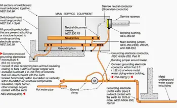
Architecture, not just connection
System grounding is about architecture. It includes:
• The bonding network that equalizes metal surfaces
• The conductors that connect equipment to the reference point
• The electrodes that establish the earth reference
• The coordination with protective devices
Together, these elements create a framework that limits voltage rise, stabilizes system behavior, and reduces stress on insulation and components. The practical relationship between grounding and bonding within this framework is explored further in our overview of how bonding maintains continuity within grounding systems.
This system-level structure is distinct from the purpose of electrical grounding, which is defined separately in our electrical grounding reference.
Why earth is only part of the system
Earth itself is not a reliable fault-clearing conductor. Soil resistance varies widely, and relying on it alone introduces uncertainty. The grounding system uses earth as a reference, not as a primary safety pathway.
Fault current control depends on electrical continuity within the bonding and conductor network. The earth connection limits system voltage relative to its surroundings, while the internal network ensures that protective devices clearly see faults and respond correctly.
The conductor that links the system to its earth reference plays a defined role within this structure, which is explained in more detail on the conductor that connects the system to its earth reference page.
Grounding systems and protective device coordination
Protective devices cannot operate properly without a predictable grounding structure. If fault energy cannot return to the source in a controlled manner, breakers and fuses may not trip when they should.
A grounding system ensures that fault paths remain stable and measurable. This allows protective devices to distinguish between normal load current and abnormal conditions, improving both safety and reliability.

This relationship is why grounding is addressed formally in national standards rather than treated as an optional installation feature. For rule interpretation and conductor relationships, see our electrical grounding code reference.
Where system grounding fits in modern installations
In residential installations, the grounding system protects occupants from energized enclosures.
In commercial buildings, it protects electronics and communication systems.
In industrial facilities, it protects personnel, equipment, and production continuity.
In utility networks, it stabilizes infrastructure that spans large geographic areas.
Explore how transformer neutral grounding behavior affects fault current paths and voltage stability in electrical networks.
The applications differ, but the architectural role of the grounding system remains the same. Regional interpretation differences between standards bodies are discussed in our CSA and NEC grounding and bonding comparison.
Grounding system behavior during abnormal conditions
When lightning energy, switching surges, or insulation failures occur, the grounding system limits how far voltage can rise relative to surrounding structures. It does not absorb energy. It controls its distribution.
This control reduces insulation breakdown, minimizes arc potential, and protects both equipment and personnel from extreme voltage stress.
Over time, this behavior improves reliability not by eliminating faults, but by shaping how the system responds to them.
Relationship to bonding
Bonding is inseparable from the performance of the grounding system. Without bonding, grounding cannot equalize potentials. Without grounding, bonding cannot establish reference.
Their coordinated relationship is explained in greater detail in our grounding and bonding overview, which focuses specifically on how these two functions support each other.
Grounding systems as a design discipline
A grounding system is not a checklist item. It is a design discipline.
It requires understanding how voltage reference, bonding, conductor routing, and electrode placement interact as a whole. When those relationships are respected, electrical systems behave calmly under abnormal conditions rather than violently.
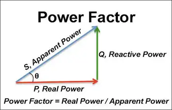
Test Your Knowledge About Power Quality!
Think you know Power Quality? Take our quick, interactive quiz and test your knowledge in minutes.
- Instantly see your results and score
- Identify strengths and areas for improvement
- Challenge yourself on real-world electrical topics
That is the difference between a system that survives faults and one that is damaged by them.
Related Pages
The following pages provide component-level and definition-level references within the grounding system structure.
