Power Factor Formula - Understanding AC Circuits
By William Conklin, Associate Editor
Power Factor Training - Improving System Efficiency
Our customized live online or in‑person group training can be delivered to your staff at your location.
- Live Online
- 6 hours Instructor-led
- Group Training Available
Download Our OSHA 4474 Fact Sheet – Establishing Boundaries Around Arc Flash Hazards

- Understand the difference between arc flash and electric shock boundaries
- Learn who may cross each boundary and under what conditions
- Apply voltage-based rules for safer approach distances
The power factor formula governs how engineers interpret electrical energy behavior in AC systems, and misunderstanding it can lead to incorrect assumptions about system loading, waveform interaction, and energy structure. It expresses the ratio of real power to apparent power, showing how voltage and current alignment shapes electrical behavior and why waveform relationships matter in professional analysis.
Power Factor Formula: How Real and Apparent Power Relate in AC Systems
The power factor formula defines the relationship between real power and apparent power in an alternating-current system, revealing how the alignment of voltage and current shapes the behavior of electrical energy in a circuit.
Unlike performance metrics, the formula does not judge efficiency or quality. It describes structure. It explains how different forms of electrical energy coexist and how their relationship is governed by waveform timing rather than by load size or equipment rating.
The formula is expressed as:
Power Factor (PF) = Real Power ÷ Apparent Power
This single ratio captures how much of the supplied electrical energy performs useful work and how much is used to support the electric and magnetic conditions required for operation, a relationship further clarified when apparent power is examined in detail on the apparent power page.
Understanding What the Formula Actually Describes
Real power represents the portion of energy that produces output, such as motion, heat, or light. Apparent power represents the total electrical presence required by the system, including energy that does not perform work but still influences waveform behavior.
The power factor formula does not attempt to correct or optimize anything. It simply shows how these two quantities relate to each other. When real power closely matches apparent power, the ratio approaches one. When the difference grows, the ratio declines. The formula remains neutral. It only reflects how energy is organized.
FREE EF Electrical Training Catalog
Download our FREE Electrical Training Catalog and explore a full range of expert-led electrical training courses.

- Live online and in-person courses available
- Real-time instruction with Q&A from industry experts
- Flexible scheduling for your convenience
This perspective becomes clearer when the relationship between real, reactive, and apparent power is viewed as a structural model rather than a performance score, which is why the mathematical structure is further expanded in the discussion of the apparent power formula.
Power Quality Analysis Training
Request a Free Power Quality Training Quotation
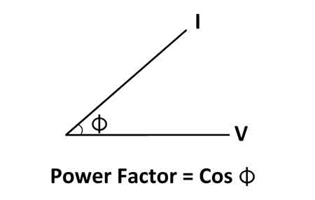
Why Power Factor Can Also Be Written as cos(θ)
Power factor is also expressed as:
PF = cos(θ)
Here, θ represents the phase angle between the voltage and current waveforms. In AC systems, voltage and current rarely rise and fall at exactly the same time. That timing difference defines how energy flows.
When voltage and current are closely aligned, the cosine of the angle is close to 1. When they are further apart, the cosine decreases. This version of the formula shows that power factor is fundamentally a waveform relationship, not a measure of consumption.
Both expressions describe the same reality from different perspectives. One uses energy quantities. The other uses waveform geometry, which is also why phase behavior is examined mathematically in the context of the reactive power formula.
What Each Part of the Formula Represents
- Real power reflects work-producing energy.
- Reactive power reflects energy that supports electric and magnetic fields.
- Apparent power reflects the combined electrical presence of both.
- Power factor expresses how those components relate as a proportion.
The formula itself does not assign value judgments. It provides a framework for understanding how alternating current behaves under different electrical conditions, including how inductive and capacitive behavior appear in systems described on the capacitive load page.
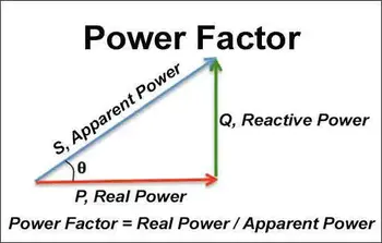
The Power Triangle as a Visual Interpretation
The power triangle offers a geometric view of the same relationship. Real power forms one side, reactive power forms the vertical side, and apparent power forms the hypotenuse. The phase angle sits between real and apparent power.


This model does not exist to solve problems. It exists to illustrate structure. It shows how electrical energy organizes itself in AC systems and why the formula behaves as it does.
Interpreting the Formula in Practical Systems
In real installations, the power factor formula helps professionals interpret how waveform behavior reflects underlying electrical conditions. Inductive and capacitive characteristics shift timing. Harmonics reshape waveforms. The formula captures those effects without prescribing action.
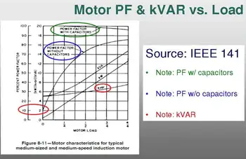
For equipment-specific interpretation, the same principles are applied in contexts such as motor operation, where waveform behavior is discussed in greater detail on the motor power factor page.
Likewise, the relationship between the phase angle and reactive components is further explored in the discussion of the reactive power formula, which expands on the structural role of non-working energy in AC systems.
Why the Power Factor Formula Matters
The power factor formula matters because it explains how electrical energy is structured, not because it tells anyone what to fix.
It provides a language for interpreting waveform relationships, understanding energy composition, and framing how alternating current behaves inside real systems, which is why it remains a core concept within the broader discipline of power quality.
The formula does not solve problems. It allows professionals to recognize them.
Frequently Asked Questions
Why does the formula matter even without calculations?
Because engineers interpret system behavior long before they calculate corrections. The formula explains how electrical energy is structured, allowing professionals to assess whether waveform relationships make sense before making numerical decisions.
Is reactive power undesirable?
Reactive power is not a defect. It is a structural requirement of many electrical systems. Problems arise not from its existence, but from misunderstanding how it shapes voltage, current, and system behavior.
Sign Up for Electricity Forum’s Power Quality Newsletter
Stay informed with our FREE Power Quality Newsletter — get the latest news, breakthrough technologies, and expert insights, delivered straight to your inbox.
Why is PF between zero and one?
Real power can never exceed apparent power, so the ratio always reflects a portion of the total.
How does the phase angle influence the formula?
The phase angle expresses how voltage and current align in time, which directly determines the PF.
Does the formula apply equally to all AC loads?
Yes. The relationship between real and apparent power is universal in AC systems, regardless of size or type.
Related Articles
To understand how the formula behaves in practical measurement, the discussion on power factor calculation shows how real and apparent components are evaluated in operating systems. The structural roles of energy components are further explored through the perspectives of apparent power and the apparent power formula.
For deeper context on non-working energy and waveform interaction, the reactive power formula explains how field support shapes AC behavior, while load characteristics are examined in the capacitive load discussion.
Motor-specific application of these principles is presented in the motor power factor analysis, with broader system implications framed within the power quality channel.
