Apparent Power Formula
By William Conklin, Associate Editor
Power Factor Training - Improving System Efficiency
Our customized live online or in‑person group training can be delivered to your staff at your location.
- Live Online
- 6 hours Instructor-led
- Group Training Available
Download Our OSHA 3875 Fact Sheet – Electrical PPE for Power Industry Workers

- Follow rules for rubber gloves, arc-rated PPE, and inspection procedures
- Learn employer obligations for testing, certification, and training
- Protect workers from arc flash and electrical shock injuries
Apparent power errors rarely cause immediate failures. Instead, they distort equipment sizing, transformer loading, conductor selection, and capacity planning, causing systems to operate closer to their thermal and protective limits than engineers expect.
This is why the apparent power formula is not just a calculation tool. It is a decision control. When it is misunderstood, the system does not become unsafe instantly. It becomes inaccurately interpreted, which is often more dangerous.
In AC systems, apparent power represents the total electrical burden placed on a source. It includes both real output and reactive circulation and is expressed in volt-amperes. The apparent power formula is:
S = V × I
Where S is apparent power in volt-amperes (VA), V is RMS voltage in volts, and I is RMS current in amperes.
This equation defines how much electrical stress a circuit imposes on generators, transformers, cables, and switchgear. It does not describe how efficiently that stress is converted into useful output. That distinction is the foundation of professional power quality judgment.
In practical engineering work, apparent power governs thermal loading and infrastructure limits. Real output governs productivity. Confusing the two leads to chronic oversizing, hidden overload exposure, or misleading capacity assumptions.
For foundational system behavior, see Apparent Power in AC Circuits. For design consequences, the distinction in Apparent Power vs Real Power defines how misinterpretation changes equipment decisions.
Power Factor and Apparent Power Judgment
Power factor (PF) determines how much of the apparent electrical demand drawn from a system is converted into useful output.
A high power factor means that most apparent demand is converted into productive work. A low PF means a significant portion circulates reactively, heating conductors, loading transformers, and consuming capacity without delivering value.
Test Your Knowledge About Power Quality!
Think you know Power Quality? Take our quick, interactive quiz and test your knowledge in minutes.
- Instantly see your results and score
- Identify strengths and areas for improvement
- Challenge yourself on real-world electrical topics
PF does not change the apparent power formula. It changes the risk of misinterpreting it.
Systems that appear lightly loaded when judged only by real output may already be operating near apparent capacity limits. Systems evaluated only by apparent demand, without PF context, may appear inefficient without revealing the underlying cause.
In applied power quality analysis, apparent values must always be interpreted alongside PF to avoid false confidence.
Measured values are commonly validated using tools such as the Apparent Power Calculator when distorted waveforms or non-linear loads are present.
Power Quality Analysis Training
Request a Free Power Quality Training Quotation
What Is Apparent Power?
Apparent power is best understood not as energy consumption, but as electrical system burden.
It represents the total electrical demand an AC circuit places on its source, including both the useful output and the reactive current required to sustain electromagnetic fields. Apparent power is measured in volt-amperes (VA) and is calculated using RMS voltage and current.
AP = Voltage × Current
or
S = V × I
Where S is apparent power in VA, V is RMS voltage in volts, and I is RMS current in amperes.
Apparent power is called “apparent” because it does not describe how much useful work the circuit performs. It describes how much electrical capacity the system must supply to sustain operation.
When low PF increases apparent power demand, automated correction strategies, such as an automatic PF controller, are often introduced to stabilize system efficiency.
Difference Between Real Power and Apparent Power
This distinction determines whether equipment is sized for productivity or for survival.
Real power, also called active or true output, is the portion of electrical energy that performs useful work. It is measured in watts.
Real Power = Voltage × Current × cos φ


or
P = V × I × cos φ
Where P is real output in watts, φ is the phase angle between voltage and current, and cos φ is the PF.
Power factor expresses how effectively apparent demand is converted into real output.
Reactive energy represents the portion required to maintain phase alignment of voltage and current but performs no useful work.
Reactive Power = Voltage × Current × sin φ
or
Q = V × I × sin φ
Reactive components, such as inductors and capacitors, store and release energy to sustain electromagnetic fields.
Together, real output, reactive circulation, and apparent demand describe how electrical energy behaves inside a system rather than merely how much current flows.
Unit of Measurement
Apparent power is measured in volt-amperes (VA). This unit reflects total electrical demand, not usable output. Equipment ratings, transformer sizing, and feeder capacity rely on apparent values because heat and mechanical stress follow the current, not the power.
Non-linear and capacitive loads frequently distort the relationship between voltage and current, making apparent power interpretation more complex than the formula alone suggests.
Power Factor Influence on Apparent Power
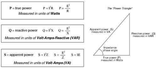
The power triangle is not a teaching diagram. It is a risk visualization model.
Apparent demand forms the hypotenuse. Real output forms the horizontal component. Reactive circulation forms the vertical component.
As PF approaches one, apparent demand approaches real output. As the power factor decreases, apparent demand increases while useful output remains constant.
Low power factor, therefore, increases electrical stress without increasing productivity. This results in higher losses, larger conductor requirements, transformer derating, and reduced system efficiency.
Electricity Today T&D Magazine Subscribe for FREE

- Timely insights from industry experts
- Practical solutions T&D engineers
- Free access to every issue
Improving PF reduces apparent demand, lowers losses, and stabilizes overall system behavior.
When the Apparent Power Formula Loses Reliability
The apparent power formula assumes sinusoidal waveforms and linear loads.
Modern electrical systems rarely meet those conditions.
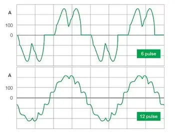
Variable frequency drives, rectifiers, LED lighting, and electronic supplies introduce harmonic distortion that can inflate RMS values while masking true thermal and protective behavior.
In such systems, apparent demand must be interpreted alongside harmonic analysis and waveform quality. The formula remains mathematically correct, but its physical meaning becomes incomplete.
This is one of the most common sources of power quality misdiagnosis in industrial environments. In facilities experiencing harmonic distortion, engineers rely on power quality and harmonics analysis to understand why apparent power trends no longer align with expected thermal behavior.
How to Calculate Apparent Power
To calculate apparent power, measure the RMS voltage and RMS current with appropriate instrumentation, then multiply them.
RMS measurement accounts for AC waveform behavior and represents the effective heating value of the signal. Once measured, the apparent power formula provides total system electrical demand.
However, the calculation should never be interpreted in isolation. It must be evaluated alongside PF, waveform distortion, and system loading context.
Related Power Formulas and Their Roles
These formulas do not compete with the apparent power formula. They explain its meaning.
Reactive Power Formula
Q = V × I × sin φ
Complex Power Formula
S = P + jQ
Power Factor Formula
PF = P / S
Volt-Amperes Formula
VA = V × I
AC Output Formula
P = V × I × cos φ
Electrical Output Formula
P = V × I
Each formula reveals a different structural aspect of electrical behavior. Together, they prevent engineers from confusing electrical burden with electrical usefulness.
When system performance degrades without obvious overloads, structured power quality troubleshooting often reveals apparent power misinterpretation as the root cause.
Professional Interpretation Summary
The apparent power formula defines electrical stress, not electrical value.
It governs transformer loading, conductor sizing, system margin, and protective design. It does not measure productivity.
Engineers who understand this distinction design systems that operate with margin. Engineers who ignore it design systems that merely appear safe.

