Electrical Resistance
By Frank Baker, Technical Editor
Electrical resistance is the property of a material or connection that limits current flow and converts part of that energy into heat. It directly determines voltage drop, power loss, conductor temperature, and overall power system efficiency.
When resistance is misunderstood or ignored, power systems do not simply become inefficient. They become unstable. Excess resistance raises conductor temperature, accelerates insulation aging, distorts voltage delivery, and reduces usable load capacity long before visible failure occurs.
For engineers, electricians, and system designers, resistance is not an abstract constant. It is the factor that governs wire sizing, termination quality, joint reliability, fault behavior, and long-term system performance. Understanding how resistance behaves in real installations is essential to preventing hidden energy loss and premature equipment degradation.
Electrical Resistance: Real-World Examples and Uses
Think of electricity moving like water through a pipe. If the pipe is narrow or obstructed, less water flows through it. Similarly, in a wire or conductor, certain materials make it harder for electrons to move freely. This obstruction results in energy loss, often as heat.
The ease with which charge moves through a material depends on its conductivity, which ultimately defines how much resistance the material presents to a circuit. Metals like copper allow current to flow easily, while rubber or glass inhibits it entirely. This behavior plays a key role in how systems are designed and protected. Discover how resistors are used in circuits to manage voltage and protect components by providing controlled resistance.
Electrical Resistance – Example Values by Material/Component
| Material/Component | Approx. Resistance | Notes |
|---|---|---|
| Copper wire (1 meter, 1mm²) | ~0.017 ohms | Very low resistance, ideal for conductors |
| Aluminum wire (1m, 1mm²) | ~0.028 ohms | Higher resistance than copper |
| Iron wire (1m, 1mm²) | ~0.10 ohms | Often used in heating elements |
| Nichrome wire (1m, 1mm²) | ~1.10 ohms | High-resistance alloy used in toasters and heaters |
| Human body (dry skin) | 1,000–100,000 ohms | Varies greatly with moisture and contact |
| Incandescent light bulb | ~240 ohms (cold) | Resistance increases when hot |
| Resistor (carbon film) | Fixed (e.g., 220 ohms) | Used to control current in circuits |
| Air (dry) | ~1 trillion ohms (insulator) | Excellent natural insulator unless ionized |
| Superconductor | 0 ohms | Only at extremely low temperatures (near absolute zero) |
Electrical Resistance Definition
Several factors that affect electrical resistance include the material type, temperature, and the dimensions of the conductor. When an electric charge moves through a material, its ease of flow depends on the material’s conductivity. A high-conductivity material allows charges to move more freely, resulting in lower resistance. The resistance of a conductor increases with its length and decreases with its cross-sectional area. Therefore, the resistance of a wire is directly related to both its physical properties and the material from which it is made. The resistance of a conductor depends heavily on its length and cross-sectional area, as outlined in our breakdown of the resistance formula.
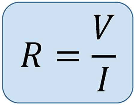
This opposing property is quantified using Ohm’s Law:
R = V / I
Where:
-
R is the resistive value in ohms
-
V is voltage (volts)
-
I is current (amperes)
Another useful expression involves material properties:
R = ρ × (L / A)
Where:
-
ρ is resistivity (material-specific)
-
L is length
-
A is the cross-sectional area
These formulas show that the longer or thinner the conductor, the harder it is for current to move through it.
Unit of Electrical Resistance – The Ohm (Ω)
The ohm is the SI unit of resistance, named after German physicist Georg Ohm. One ohm is defined as the resistance between two points of a conductor when a potential difference of one volt causes a current of one ampere to flow.
Common multiples:
-
kΩ (kilo-ohm) = 1,000 ohms
-
MΩ (mega-ohm) = 1,000,000 ohms
Resistance can be measured with a multimeter and is especially important in designing and troubleshooting power and electronic circuits. To understand how voltage and resistance interact in a circuit, see our guide on Ohm’s Law.
Ohm’s Law and Circuit Function
Ohm’s Law helps us understand how voltage, current, and resistance relate. For example:
-
Increasing the resistive load decreases the current.
-
Increasing the voltage with a fixed resistance increases the current.
These principles help control energy flow, prevent overloads, and design efficient systems.
Measuring and Expressing Opposition
One ohm means that a current of one ampere flows when one volt is applied. Components with fixed values, like resistors, are labelled accordingly—e.g., 100 Ω, 1 kΩ, or 1 MΩ.
To measure a material's current-limiting capacity, a digital multimeter is used. It applies a small voltage and calculates the resulting current flow to determine the opposition level. If you're working with different wire types, explore the unit of electrical resistance for conversion insights and resistance ranges.
Real-World Examples of Resistance
-
Heating Elements: Toasters, ovens, and electric heaters utilize high-resistance materials, such as nichrome wire.
-
Power Transmission: Long-distance wires are designed with low resistance to reduce energy loss as heat.
-
Electronic Components: Resistors regulate current in circuits, protecting components from overload.
For real-world scenarios involving current flow, our article on voltage drop explains how resistance affects efficiency over distance.
Factors Affecting Electrical Resistance
-
The resistance of a conductor depends on:
-
Material – copper vs. aluminum vs. nichrome
-
Length – longer wires restrict current more
-
Thickness – wider wires allow easier flow
-
Temperature – many materials resist current more when heated
Thus, the resistance of a wire can vary dramatically depending on where and how it’s used. Materials with high conductivity (like silver or copper) allow electrons to move with minimal restriction, whereas poor conductors like rubber greatly hinder charge movement.
-
Superconductors – Zero Resistance?
In some materials, when cooled to extremely low temperatures, resistance drops to zero. These superconductors enable electricity to flow without energy loss, but their use is limited to specialized fields, such as MRI machines or experimental power lines, due to cost and cooling requirements.
Frequently Asked Questions
What causes electrical resistance?
It results from collisions between electrons and atoms in a conductor, which convert energy into heat.
What is the formula for calculating it?
R = V/I or R = ρ × (L / A)
How is it measured?
With a multimeter in ohms (Ω), using a small test voltage, and measuring current. Learn how instruments like a digital multimeter are used to measure opposition to current flow in systems.
Why is this concept important?
It controls current flow, prevents damage, and enables functions like heating or dimming.

Can resistance ever be zero?
Yes, in superconductors under specific extreme conditions.
Electrical resistance is a foundational concept in understanding how electricity behaves in materials and systems. From household wiring to high-voltage power lines and sensitive electronics, it plays a crucial role in determining safety, efficiency, and performance. For a broader view on electric flow and material response, read about electrical conductivity and current electricity.
Related Articles