Electrical Units Explained
Electrical units determine whether a decision is accurate or dangerously wrong. Every voltage rating, current measurement, resistance value, and power calculation depends on using the correct unit in the correct context. When units are misunderstood or misapplied, equipment is mis-sized, protection is mis-coordinated, and safety margins quietly disappear.
Electrical units measure voltage, current, resistance, and power in systems, but their real purpose is not description; it is judgment. Engineers rely on them to verify conductor loading, technicians use them to confirm operating conditions, and facility managers depend on them to assess energy use and system reliability. A single unit error can turn a compliant design into a failure risk.
This is why electrical units are not merely academic symbols. They control how laws are applied, how equipment is rated, and how performance is interpreted. Confusing amperes with watts, or resistance with impedance, leads directly to incorrect conclusions about heat, capacity, efficiency, and safety.
Understanding electrical units, therefore, is not about memorizing definitions. It is about making correct measurement decisions, interpreting results accurately, and applying principles with confidence in real systems.
Key Concepts of Electrical Units
Electrical units form the shared language of electricity. They allow us to describe how much current flows through a conductor, how strongly voltage pushes that current, how much resistance limits it, and how much power is ultimately delivered to a load. Without standardized units, it would be impossible to design power systems, compare measurements, or diagnose problems consistently.
In everyday use, electrical units appear everywhere, from appliance nameplates and breaker ratings to utility bills and industrial specifications. A technician checking current draw, an engineer calculating voltage drop, or a facility manager monitoring energy usage are all relying on these units to make informed decisions. Understanding what each unit represents helps connect theory to real-world behavior.
The sections below explain the most common electrical units, how they are defined, and why they matter in practical electrical work. Together, they provide the foundation for interpreting measurements, applying laws, and understanding how electricity behaves under different conditions. A solid foundation in Electricity Fundamentals ensures professionals correctly interpret volts, amperes, ohms, and watts before applying them in design, measurement, or safety decisions.
Ampere
The ampere measures electric current, or the rate at which electricity flows through a conductor. In practical terms, it tells you how hard a circuit is working. A higher current means more activity and greater demand on wires, breakers, and equipment.
In everyday use, amperes appear on breaker ratings, motor nameplates, and panels. For example, a typical household electrical circuit may be rated at 15 or 20 amperes, limiting how much current devices can safely draw without overheating conductors or tripping protection.
Coulomb
The coulomb measures electric charge. It represents the total quantity of electricity moving through a circuit, rather than how fast it flows. One coulomb equals the amount of charge delivered by a current of one ampere flowing for one second.
While the coulomb is not commonly displayed on power equipment, it underpins how current and energy are calculated. Battery capacity, static discharge, and stored charge calculations all rely on this unit in the background.
Electron Volt
The electron volt is a unit of energy used mainly in electronics, semiconductors, and physics. It describes the amount of energy gained by a single electron when it moves through a potential difference of 1 volt.
Although electricians rarely work directly with electron volts, the concept is important in understanding how components like diodes, transistors, and photovoltaic cells behave at the atomic level. It also appears in discussions of insulation breakdown and semiconductor switching behavior. For those managing voltage drop in long circuits, we provide a helpful voltage drop calculator and related formulas to ensure system efficiency.
Faraday
The henry measures inductance, or a component’s ability to store energy in a magnetic field when current changes. Inductance resists sudden changes in current flow and plays a key role in AC systems.
Inductance measured in henries appears in transformers, motors, reactors, and inductors used in power supplies. For example, inductance helps smooth current in power conversion equipment and limits fault currents during switching events.
Henry
The henry is a unit of either self-inductance or mutual inductance, abbreviated h (or hy), and named for the American physicist Joseph Henry. One henry is the value of self-inductance in a closed circuit or coil in which one volt is produced by a variation of the inducing current of one ampere per second. One henry is also the value of the mutual inductance of two coils arranged such that an electromotive force of one volt is induced in one if the current in the other is changing at a rate of one ampere per second.
Ohm
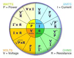
The ohm measures electrical resistance, which limits the amount of current that can flow for a given voltage. Resistance converts some energy into heat, which is why the size and material of the conductor matter.

Ohms are used constantly in electrical work. Resistance affects voltage drop along conductors, cable heating, and load operation. Understanding resistance is essential when applying Ohm’s Law to calculate current, power, and energy loss in a circuit. Resistance, measured in ohms, determines how much a circuit resists current, as explained in our page on Ohm’s Law.
Siemens
The Siemens measures conductance, which is the ease with which current flows. It is the inverse of resistance and is especially useful when dealing with materials or paths that carry leakage current.
Conductance measured in siemens is often used in grounding studies, insulation testing, and moisture detection. For example, insulation resistance testers may rely on conductance concepts to identify contamination or degradation.
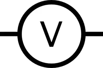
Volt
The volt measures electrical potential difference, or how strongly electricity is pushed through a circuit. Voltage determines how much energy is available to move charge from one point to another.
Most household outlets supply about 120 volts in North America, while industrial systems commonly use higher voltages such as 480 volts to reduce current and improve efficiency. Voltage levels are carefully selected to balance safety, performance, and energy losses. Explore how devices like ammeters and voltmeters are used to measure current and voltage across components. To better understand how voltage is measured and expressed in volts, see our guide on what is voltage.
Watt
The watt measures electrical power, which is the rate at which energy is used or delivered. It combines voltage and current into a single value that reflects real power output.
Appliances, motors, and lighting are typically rated in watts. A 1000-watt heater converts energy into heat much faster than a 60-watt light bulb converts it into light. Power calculations are essential for sizing equipment and preventing overloads. Learn how a watt defines power in systems and its relationship to volts and amperes through Watts' Law.
Weber
The Weber is a unit of magnetic flux, which describes the amount of magnetic field passing through a given area. Magnetic flux is closely tied to the operation of transformers, generators, and motors.
Flux measured in webers determines how effectively energy can be transferred between windings. In power equipment, controlling magnetic flux is essential for efficiency, voltage control, and preventing core saturation.