What does an Ammeter Measure?
By Frank Baker, Associate Editor
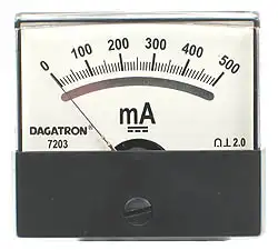
An ammeter measures the electric current flowing through a circuit and displays it in amperes (A). Becoming part of the current path allows technicians and engineers to observe the amount of electrical charge moving through a conductor at any given moment. This measurement is essential for verifying load behavior, identifying abnormal operating conditions, and confirming whether equipment is performing within its intended electrical limits.
How does an Ammeter Measure Current?
An ammeter displays the rate of electric charge flowing through a conductor. Current is measured in amperes, commonly called amps, and the instrument takes its name directly from that unit. You may occasionally see the word written as “ampmeter,” but “ammeter” is the correct term.
To obtain an accurate reading, an ammeter must be connected in series with the circuit or component being tested. This placement ensures that all of the current flowing to the load also passes through the meter. Because the meter becomes part of the circuit, it is designed with very low internal resistance so it does not significantly affect normal operation during measurement.
This operating principle makes more sense once you understand basic electricity fundamentals, including how voltage, current, and resistance interact.
In practice, ammeters allow technicians to verify expected current draw, confirm whether equipment is operating within its rated limits, and detect abnormal conditions such as overloads or short circuits. Whether applied to small electronic circuits or large industrial motors, the purpose remains the same: observe current flow without disrupting the system being tested.
The ampere itself is explained in more detail in our guide on what is an ampere, which also shows how current relates to voltage and resistance in electrical units.
To see how ammeters fit into broader measurement tools, check out our guide on what is a voltmeter and what is a multimeter, which measure multiple electrical properties.
Understanding how an ammeter functions also becomes clearer when viewed alongside other instruments. Unlike voltmeters, which are connected in parallel, or ohmmeters, which require an unenergized circuit, an ammeter must carry live current during the measurement process. This requirement shapes both its internal design and its safe field application. The ADC is read by a microcomputer, which performs calculations to display the current through the resistor.
How an Ammeter Works
An ammeter is named after the ampere, the unit of electrical current. While the spelling “ampmeter” occasionally appears, “ammeter” is the correct technical term. The instrument exists for one purpose: to measure the current passing through a conductor at a specific point in time.
Inside the instrument, current passes through a precision resistor known as a shunt. As current flows through this shunt, it produces a very small voltage that is directly proportional to the current. That voltage becomes the signal the meter uses to determine the current value.
In older analog designs, this signal influences a magnetic mechanism that moves a needle across a calibrated scale. In modern instruments, the voltage across the shunt is measured electronically and displayed numerically. In both cases, the underlying principle is the same: measure current indirectly by observing its effect on a known resistance.
The success of this approach depends on careful design. If the internal resistance were too high, the meter would distort the measurement and interfere with normal circuit operation. Keeping resistance low allows the ammeter to do its job without becoming part of the problem it is trying to diagnose.
Accurate current measurement also depends on understanding what is electrical resistance and how it affects current flow, especially in low-resistance ammeter designs.
Types and Mechanisms
Several types of ammeters are used today, each suited to different applications and working environments.
Analog ammeters use a moving needle and scale to display current. These instruments provide a continuous visual indication of changing current, which can be helpful when observing start-up conditions, fluctuating loads, or unstable circuits. They are simple, durable, and still used in many fixed installations.
Digital ammeters display current as a numerical value. They rely on electronic measurement of the voltage across an internal shunt and convert it to amperes. Digital meters offer higher accuracy, better resolution, and often include additional features such as data storage or integration with other measurements.
Clamp meters measure current without opening the circuit. By sensing the magnetic field around a conductor, they allow quick checks of current in live systems. This makes them particularly useful for high-current applications or situations where interrupting power is impractical.
Current transformer ammeters are used in high-current AC systems. A current transformer reduces large primary currents to a smaller, proportional value that can be safely measured by a meter. These are commonly found in switchgear, panels, and power distribution equipment.
Shunts and Operation
The shunt resistor is central to most ammeter designs. It is manufactured with very low resistance and precise tolerances, ensuring a predictable voltage drop across a wide range of currents.
In analog meters, the shunt diverts most of the current around the sensitive measuring mechanism, protecting it from damage. In digital meters, the shunt provides the reference voltage that the electronics use to calculate current using Ohm’s law.


Because shunts can be scaled, this method allows ammeters to measure anything from tiny currents in electronic circuits to very large currents in industrial systems. Accurate shunt design is one of the reasons modern ammeters can be both sensitive and robust.
Applications in Practice
Ammeters are essential tools for electrical testing, troubleshooting, and system verification. They are routinely used to identify overload conditions, confirm proper equipment operation, and detect faults that may not be visible through voltage measurements alone.
In residential and commercial work, current measurements help verify circuit loading and ensure protective devices are properly sized. In industrial settings, monitoring motor current can reveal mechanical problems, process changes, or developing failures before damage occurs.
Common applications include:
-
Automotive diagnostics, to identify battery drains and charging problems.
-
Solar and battery systems, to monitor charging and discharging behavior.
-
Industrial maintenance, to reveal abnormal motor loading or imbalance.
-
Appliance servicing, to confirm devices operate within expected current limits.
-
Power distribution systems, to ensure conductors and protective equipment remain within safe capacity.
Specialized ammeters are also used for very small currents in control circuits and instrumentation, while integrating ammeters track current over time to determine total electrical charge delivered by a system.
Related Articles