Resistance Formula Explained
By R.W. Hurst, Editor
The resistance formula, R = V/I, shows how voltage and current determine opposition in a circuit. Central to Ohm’s Law, it is widely applied in electronics, power distribution, and engineering to calculate resistance, ensure efficiency, and design reliable electrical systems.
Quick Reference: Resistance Formula
Electrical circuits are essential for powering our daily lives, and understanding the factors that influence their performance is key to optimizing their efficiency. A critical aspect of electrical circuits is the Resistance they encounter, which directly affects the flow of electrons. Based on Ohm's law, the formula helps us analyze and manipulate various elements within a circuit. Topics like electrical resistance and the unit of electrical resistance expand on how opposition to current flow is measured and applied in engineering.
The flow of charge in any conductor depends on material properties and circuit design, where individual resistances combine differently depending on series or parallel circuit arrangements. According to law resistance principles, the total parallel resistance is always less than the smallest branch, and values are measured as resistance in ohms. Materials with the smallest resistivities like copper conduct efficiently, though their performance is affected by the temperature coefficient of resistivity, which alters conduction as heat rises. For visual examples and diagrams, resources such as Wikimedia Commons provide helpful illustrations.
Ohm's Law
Ohm's law is fundamental to understanding electrical circuits. It states that the Voltage across a conductor is directly proportional to the electric Current passing through it, and the constant of proportionality is the electrical Resistance. In mathematical terms, Ohm's law can be expressed as V = IR, where V is the Voltage, I is the electric Current, and R is the Resistance. Related principles, including Ampere’s Law and the Biot-Savart Law, further explain how current and magnetic fields interact with resistance in circuits.
The formula R = ρ(L/A) is derived from Ohm's law and describes how R depends on the conductor's material, length (L), and cross-sectional area (A). The resistivity (ρ) is a property unique to the conductor material and represents its ability to impede the flow of electrons. Different materials, such as copper or aluminum, have different resistivities, affecting the overall electrical R.
Wire length and cross-sectional area play a significant role in determining a conductor's R. As the wire length increases, so does the R, as electrons face more obstacles. Conversely, increasing the cross-sectional area reduces R, allowing more electrons to flow through the conductor simultaneously. This inverse relationship between R and cross-sectional area is vital in designing circuits to minimize energy loss and optimize efficiency.
Various factors influence the resistivity of conductor material. For instance, impurities in the material can hinder electron flow, thereby increasing resistivity. Additionally, the arrangement of atoms within the material's lattice structure affects the ease with which electrons can pass. Finally, the temperature coefficient is crucial, as fluctuations can alter resistivity. Generally, R increases with higher temperatures as atoms vibrate more and impede electron flow.
Resistance and conductance differ in their relationship to the flow of electrons. While R quantifies the opposition a conductor presents to the flow of electrons, conductance represents the ease with which electrons can pass. Mathematically, conductance (G) is the reciprocal of Resistance (R), and is measured in Siemens (S):
G = 1/R
The formula can be used to calculate power dissipation in a circuit. Power (P) is the product of Voltage (V) and current (I): P = VI. Using Ohm's law, we can substitute V = IR into the power formula to obtain P = I^2R. This equation demonstrates that higher R results in greater power dissipation, manifesting as heat. Hence, managing R is essential in preventing energy loss and maintaining circuit efficiency.
Ohm's law defines a mathematical relationship involving V, R, and current (I) within an electrical component. Ohm, denoted by the Greek letter omega (Ω), is the unit of measurement for R. Furthermore, Ohm's law can derive a power equation by computing electrical power, quantified in watts. Subsequently, Gustav Kirchhoff built upon Ohm's foundational work and introduced Kirchhoff's rules, two equalities addressing current and Voltage in an electric circuit model.
Ohm's law outlines the fundamental principles of electrical circuits, highlighting the interdependence between voltage, current, and resistance. This relationship can be expressed in three different formulas:
V = I × R (Voltage equals Current multiplied by Resistance)
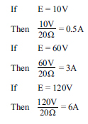
R = V / I (Resistance equals Voltage divided by Current)
I = V / R (Current equals Voltage divided by Resistance)
These formulas illustrate the interconnection of voltage, current, and resistance in electrical circuits. By manipulating these relationships, we can analyze the behaviour of circuits, troubleshoot issues, and optimize efficiency.
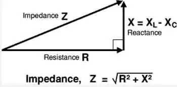
The significance of Ohm's law extends beyond its mathematical representation. It forms the basis for understanding various electrical phenomena, including power dissipation, energy consumption, and the impact of R on the performance of electrical components. The role of resistance is closely tied to capacitance and inductance, which determine energy storage and reactance in alternating current systems.
As we explore the vast applications of electrical circuits, understanding the formula allows us to make informed decisions in choosing conductor materials, adjusting wire length and cross-sectional area, and considering temperature fluctuations. With an understanding of how these factors interact, we can continue to innovate, create, and harness the power of electricity to achieve a brighter future.