Voltage Drop Explained
By William Conklin, Associate Editor

Voltage drop is the reduction in electrical voltage that occurs as current travels through a conductor, caused by resistance and circuit length. It determines how much usable voltage actually reaches equipment, and directly affects performance, efficiency, and reliability in real electrical systems.
A small voltage drop may go unnoticed. Excessive voltage drop changes how equipment behaves. Motors overheat, lighting output falls, controls lose stability, and energy is wasted as heat in the conductors rather than being delivered to the load. These effects often appear as unrelated operational problems, even though the root cause is wiring design.
Voltage drop is therefore not simply a calculation. It is a design judgment that influences conductor sizing, circuit layout, and system margins. Every additional meter of cable, every ampere of load, and every reduction in conductor size shifts the balance between efficiency, safety, and compliance. Poor decisions rarely cause immediate failure, but they steadily degrade system performance and shorten equipment life.
Voltage Drop in Conductors
Voltage drop occurs whenever current flows through a conductor and encounters electrical resistance. Some loss is unavoidable, but the amount of loss determines whether a circuit operates as intended or becomes a hidden source of inefficiency. Conductor size, run length, load current, material, and system configuration all interact to shape that outcome.
In practical installations, voltage drop most often results from long cable runs, undersized conductors, or higher-resistance materials. The longer the conductor and the smaller its cross-section, the more voltage is lost before it reaches the load. This is why conductor selection is not only a code obligation, but a reliability decision.
In large buildings, agricultural systems, and industrial facilities, voltage drop can become significant enough to alter equipment behavior under normal operating conditions. Motors may struggle during startup, lighting levels may fluctuate with load, and protective devices may respond unpredictably as voltage falls below design thresholds.
Understanding and evaluating voltage drop allow electricians, engineers, and facility managers to prevent these problems before they occur. Proper calculation confirms whether a conductor is correctly sized or whether system adjustments are needed to maintain stable, efficient voltage delivery throughout the circuit.
For readers who want to explore formal instruction related to power quality and system efficiency, structured programs such as Power Quality Analysis Training, Power Factor Training, and the option to Request a Free Power Quality Training Quotation are best presented as dedicated learning resources rather than embedded within the technical explanation of voltage drop.
Keeping these learning pathways in a clearly separated training or resource area allows the article itself to remain focused on voltage drop as an engineering and design topic, while still giving interested readers a natural transition point to professional education. This separation protects the article’s editorial authority, maintains single-intent clarity, and supports stronger AI and human trust signals without reducing the visibility or value of the training offerings.
Voltage Drop per 100 Feet of Copper Wire (Single Phase, 60 Hz, 75°C, 120V Circuit)
Voltage drop is not just influenced by current. Conductor size and circuit length play an equally important role. Even a correctly protected circuit can experience unacceptable voltage loss if the wire size is too small for the distance involved.
Because of this, voltage drop limits are often expressed as a percentage of system voltage. Many designers aim for a conservative target, such as 2 percent on branch circuits, to ensure reliable equipment operation and consistent performance under load. Staying within these limits usually requires increasing conductor size as distance or current increases.
Electricians often refer to Voltage Drop reference tables like this when checking whether a conductor size is reasonable for a given run length and load. The values shown here illustrate how conductor size, current, and distance interact under typical conditions.
Voltage Drop vs Wire Size (AWG)
(Values are approximate, in volts, for a 2% limit)
| Wire Size (AWG) | Max Current (Amps) | Max Distance (Feet) | Voltage Drop (at max distance) |
|---|---|---|---|
| 14 | 15 | 50 | 2.4 V |
| 12 | 20 | 60 | 2.4 V |
| 10 | 30 | 80 | 2.4 V |
| 8 | 40 | 100 | 2.4 V |
| 6 | 55 | 130 | 2.4 V |
| 4 | 70 | 160 | 2.4 V |
| 2 | 95 | 200 | 2.4 V |
| 1/0 | 125 | 250 | 2.4 V |
Key Takeaways
Larger conductors result in less voltage drop because lower resistance allows current to flow more efficiently.
As circuit length increases, conductor size must increase to maintain acceptable voltage levels.
Voltage drop limits are design targets, not absolutes, but staying well below maximum values improves reliability and equipment lifespan.
Even when circuits meet minimum code requirements, excessive voltage drop can still cause performance problems.
How is this solved?
The usual fix for voltage drop is simple: use a larger conductor to reduce the resistance. In practice, electricians consider the run length, load, and budget, then choose the next wire size that keeps the drop within acceptable limits. The goal is not perfection but a workable balance between performance and cost.
How do you calculate voltage drop?
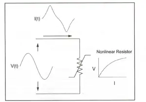
Voltage drop is the reduction in voltage that occurs as current flows through a resistor. To see how much is being lost, you measure the voltage at two points in the circuit and compare the values. In basic DC circuits, the individual drops across each load should add up to the supply voltage. If they don’t, something in the circuit isn’t behaving as expected.
In DC circuits and AC resistive circuits, the total of all the voltage drops across series-connected loads should add up to the V applied to the circuit (Figure 1).


Fig. 1. Measuring voltage drops across loads
Read our companion article Voltage Drop Calculator. For more information, see our article: Voltage Drop Formula.
AS3000 Example
The AS3000 method gives a quick way to estimate voltage drop without digging through detailed resistance tables. It lists how many amps each cable size can carry per percentage of allowable drop. You multiply the load current by the cable length, then divide by the value in the table. The result gives you the drop as a percentage. It’s meant as a practical shortcut, not a replacement for full design calculations.
For example, a 30m run of 6 mm² cable carrying 3-phase 32A will result in a 1.5% drop: 32A × 30m = 960A / 615 = 1.5%.
Learn more about real-world voltage drop issues on our Voltage Dropping in Power Quality page.
Using a Voltmeter
Checking voltage drop with a meter is straightforward. Start by making sure the meter range is high enough so you don’t overload it. Place the common lead on the circuit’s reference point and touch the red lead to the spot you want to measure. Comparing readings at different points tells you where voltage is being lost and whether the drop is within a reasonable limit.
Related Articles