Total Impedance Calculator


total impedance calculator

Total impedance calculator determines total opposition in AC circuits by combining resistance, inductive reactance, and capacitive reactance. Input R, L, C, and frequency to find Z in ohms for accurate analysis in power distribution, filters, or signal systems.


Total Impedance Calculator: Real-World Examples and Uses

A total impedance calculator helps you quickly determine the combined impedance of resistors, inductors, and capacitors in AC circuits. By inputting values for resistance (R), inductive reactance (XL), and capacitive reactance (XC), you can calculate total impedance (Z) for both series and parallel configurations, making circuit analysis faster, more accurate, and easier to understand. A total impedance calculator is a powerful tool used by electrical engineers, technicians, and students to determine the impedance in RLC circuits, whether in series or parallel. These calculators simplify complex calculations involving resistance, inductance, and capacitance by processing formulas that would otherwise require manual computation with complex numbers.

Whether you are designing a power supply, analyzing signal transmission, or optimizing filter performance, a total impedance calculator helps ensure accuracy and efficiency. It is especially valuable when analyzing the behaviour of AC circuits across different frequency ranges in hertz.


What Is Total Impedance?

Total impedance refers to the combined opposition that a circuit presents to the flow of alternating current. It takes into account both resistance (R) and reactance (X), expressed as a single value in ohm (Ω). The two primary types of reactance are:

  • Inductive reactance (caused by coils or inductors)

  • Capacitive reactance (caused by capacitors)

These values change depending on the circuit's frequency, making tools like a total impedance calculator essential for real-time circuit analysis.


Who Uses a Total Impedance Calculator?

  • Electrical engineers use it in power systems, communications, and control circuits.

  • Technicians rely on it to verify component ratings and troubleshoot systems.

  • Educators and students apply it in academic settings for lab work and theoretical analysis.

  • Industrial maintenance professionals use it to evaluate equipment behavior under various loads.

It is particularly helpful when working with an RLC circuit impedance calculation where both inductance (L) and capacitance (C) are present.


What Does a Total Impedance Calculator Do?

A good impedance calculator lets you:

  • Enter known values like resistance (R), inductance L and capacitance C, and frequency in hertz.

  • Automatically compute impedance for either series RLC circuit or parallel RLC circuit setups.

  • Show results using the correct impedance formula, including both magnitude and phase.

  • Factor in angular frequency in rad, derived from ω=2πf\omega = 2\pi fω=2πf, where fff is frequency.

  • Solve expressions like 1ωC\frac{1}{\omega C}ωC1​ or frac 1 omega, commonly used in capacitive reactance calculations.

The result is a fast, accurate way to determine the impedance and analyze AC circuit behavior.


Key Concepts Behind the Calculator


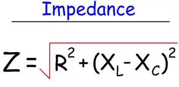
1. Impedance Formula (Z)

This requires working with complex numbers to calculate both magnitude and phase angle.


2. Reactance Components

  • Inductor and capacitor components contribute to the reactive part of the impedance.

  • Capacitive reactance

  • Inductive reactance

These values vary with frequency and affect circuit resonance and behavior.


Why Use a Total Impedance Calculator?

Without a calculator, these formulas can be tedious to evaluate manually—especially when working in real time or across wide frequency in hertz ranges. A calculator ensures:

  • Greater accuracy in design and testing

  • Time-saving analysis for troubleshooting

  • Safer decision-making for load balancing and component selection

In power electronics, knowing the rlc circuit impedance helps prevent equipment damage and improves system efficiency.

A total impedance calculator is an essential tool for modern electrical work. It brings together the core principles of AC circuit analysis—resistance, inductance, capacitance, and frequency—into one user-friendly interface. Whether you're designing systems, teaching students, or maintaining equipment, using this tool helps you quickly and reliably calculate the impedance and make informed decisions.


Related Articles


Related News

Electricity Production

Electricity production converts primary energy into power via thermal, hydro, wind, and solar systems, optimizing efficiency, capacity factor, grid stability, transmission reliability, and emissions through turbines, generators, inverters, and advanced SCADA control.   The Complete Guide to Electricity Production Electricity Production continues to grow around the world, from a variety of energy power sources. In terms of world electricity generation, the US Department of Energy predicts advances strongly from 2004 to 2030. Global production increases by 2.4 percent per year over the projection period, from 16,424 billion kilowatthours in 2004 to 30,364 billion kilowatthours in 2030. Much of the growth in…
View more

Electromagnetic Induction

Electromagnetic induction is the process of generating electric current by changing a magnetic field, forming the basis for transformers, generators, and electric motors in power generation and energy conversion systems.   The Complete Guide to Electromagnetic Induction Its underlying principles, Faraday's Law and Lenz's Law, explain the phenomena occurring when magnetic fields interact with conductors. At the same time, its various applications, such as electric generators, transformers, induction heating, and wireless charging, have revolutionized our daily lives. As we continue to explore and understand this intricacy, we can look forward to even more innovations and advancements in electricity and magnetism.…
View more

Types of Electricity - Static and Current

Types of electricity include static electricity and current electricity, which flows as direct current or alternating current. These forms explain how electric charge builds up, moves through conductors, and powers devices and electrical systems.   Understanding Types of Electricity Electricity is commonly described in different ways, but at its core it behaves in only two fundamental forms: electricity that is stored in place and electricity that flows. This distinction helps avoid a common source of confusion, because the way electricity is generated does not define its type. Whether electricity comes from wind, water, solar panels, or fossil fuels, the output…
View more

Hydroelectricity Explained

Hydroelectricity converts hydropower into grid-ready electricity using dams, penstocks, turbines, and generators, enabling renewable baseload, pumped storage, high efficiency, and low emissions for resilient power systems with load balancing, frequency regulation, and strong capacity factors.   Understanding How Hydroelectricity Works Hydroelectricity is another term for power generated by harnessing the power of damming rivers and moving water into generating plants. Not necessarily falling water, just moving water. There are many famous such Hydroelectricity stations in the world, not the least of them at Niagara Falls, Grand Coulee and Boulder Dam and the three gorges dam in China . In the past, small…
View more

Ohm's Law Formula

The Ohm's Law formula is a cornerstone of electrical engineering, serving as a basis for analyzing and designing electric circuits. Its applications range from determining the appropriate values of electrical components to predicting the behaviour of complex systems. By exploring the relationship between voltage, current, and resistance and their connections with other fundamental laws in electromagnetism, we can gain a deeper understanding of the principles that govern the flow of electricity and its conversion into other forms of energy. Ohm's Law states that the relationship between voltage, current, and resistance. This law, named after its discoverer Georg Simon Ohm, has…
View more

Capacitors in Series Explained

Capacitors in series lower the total capacitance but increase voltage handling. This configuration is widely used in electronics, circuit design, and energy storage to balance voltage and improve reliability.   Understanding Capacitors in Series Capacitors in series describe a circuit configuration in which capacitors are connected end to end, affecting the capacitance and voltage distribution. They play a critical role in various electronic applications, and understanding their characteristics, advantages, and potential drawbacks is essential for designing and implementing successful circuits. By mastering the concepts of capacitance, voltage distribution, and energy storage, one can leverage capacitors in series to design optimal…
View more

Sign Up for Electricity Forum’s Newsletter

Stay informed with our FREE Newsletter — get the latest news, breakthrough technologies, and expert insights, delivered straight to your inbox.

Electricity Today T&D Magazine Subscribe for FREE

Stay informed with the latest T&D policies and technologies.
  • Timely insights from industry experts
  • Practical solutions T&D engineers
  • Free access to every issue

Live Online & In-person Group Training

Advantages To Instructor-Led Training – Instructor-Led Course, Customized Training, Multiple Locations, Economical, CEU Credits, Course Discounts.

Request For Quotation

Whether you would prefer Live Online or In-Person instruction, our electrical training courses can be tailored to meet your company's specific requirements and delivered to your employees in one location or at various locations.