What is an Electrical Fault?
By R.W. Hurst, Editor
An electrical fault occurs when a system or piece of equipment departs from its normal operating state, resulting in abnormal current flow. This can result in overheating, equipment damage, or safety risks. Protective devices isolate faults to preserve safety and reliability.
What is an Electrical Fault?
Electrical faults can occur for various reasons, including equipment failure, environmental conditions, and human error. Some common causes of electrical faults include faulty wiring, damaged insulation, overloaded circuits, lightning strikes, power surges, and voltage fluctuations.
-
Equipment issues: faulty wiring, broken insulation, overloaded circuits
-
Environmental conditions: moisture, lightning, dust, or tree contact
-
Human error: poor installation, neglect, or unsafe work practices
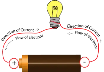
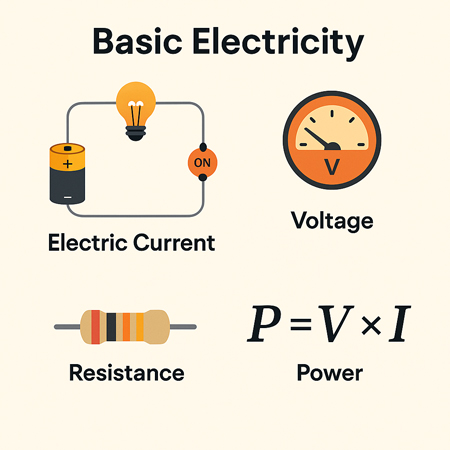
The most common fault categories include open-circuit faults, short-circuit faults, and ground faults. An open circuit fault occurs when a break in the circuit prevents current from flowing. A short circuit occurs when an unintended connection between two points allows an excessive amount of current to flow. A ground fault occurs when an unintended connection between the electrical circuit and the ground creates a shock hazard. Faults often relate to excessive current flow, which can be better understood through Ohm’s Law and its role in determining resistance, voltage, and current relationships.
A balanced fault is a condition in which all three phases of a three-phase system are shorted to ground or to each other. In this type of fault, the system remains balanced, and the fault current is limited. Understanding basic electricity is essential to grasp how faults disrupt the normal flow of current in a circuit.
Classifications of Electrical Faults
Electrical faults can be categorized into several groups to help engineers understand their causes and plan effective protective measures.
Transient vs. Permanent Faults: Transient faults, such as those caused by a lightning strike or temporary contact with a tree branch, clear on their own once the source is removed. Permanent faults, on the other hand, require repair before normal operation can resume, such as when insulation fails or a conductor breaks.
Symmetric vs. Asymmetric Faults: A symmetric fault affects all three phases of a system equally, and although rare, it can cause severe damage due to the high fault currents it generates. Asymmetric faults are far more common, involving one or two phases, and they create an unbalanced condition in the system.
Internal vs. External Faults: Internal faults occur within equipment, such as transformers, generators, or motors, often due to insulation breakdown or winding damage. External faults originate outside the equipment, caused by conditions such as storm damage, contact with foreign objects, or human error.
Types of Electrical Faults in Power Systems
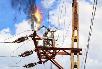
A line-to-ground fault occurs when one of the conductors in a circuit comes in contact with the ground. This can happen due to faulty insulation, damaged equipment, or environmental conditions. A common example is a lightning strike creating a transient line-to-ground fault that trips breakers on a distribution system.
Other major types include:
-
Line-to-ground: conductor touches ground, causing shock risk
-
Open circuit: broken wires or components stop current flow
-
Phase fault: phases contact each other or ground
-
Short circuit: an unintended connection allows excessive current
-
Single-phase: limited to one phase, but still damaging
-
Arc fault: current jumps an air gap, creating sparks and fire risk
-
Balanced vs unbalanced: equal current in phases vs uneven distribution
Rodents chewing through insulation in attics or utility spaces often cause arc faults, showing how even small intrusions can lead to dangerous electrical events. When discussing ground faults and protective systems, it’s useful to revisit the conductor definition, since conductors are the pathways through which electrical energy travels and where faults typically occur.
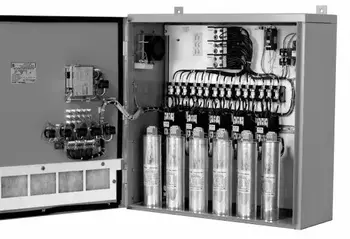
Electrical Fault Protection Systems and Safety Devices
A circuit breaker is a device that automatically interrupts the flow of current in a circuit when it detects a fault. It is an essential safety device that helps prevent fires and other hazards.
When a circuit is interrupted, the flow of current in the circuit is stopped. This can happen for various reasons, including a circuit fault, a switch or breaker opening, or other similar issues.
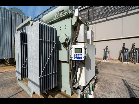
In an electric power system, faults can cause significant damage to system equipment and result in power outages. Power system equipment includes transformers, generators, and other devices that are used to generate, transmit, and distribute power.
-
Circuit breakers: interrupt current when faults are detected
-
Relays: monitor and signal breakers to operate
-
Fuses: provide overcurrent protection in smaller systems
-
GFCIs: stop leakage current to ground instantly
-
AFCIs: detect arc faults to prevent electrical fires
Modern protective relay schemes, such as distance relays, differential relays, and overcurrent relays, provide precise and selective fault detection in high-voltage power systems. Engineers also use fault current analysis and time–current coordination studies to ensure that devices operate in the right order, isolating only the affected portion of the network.
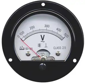
Voltage drop refers to the reduction in voltage that occurs when current flows through a circuit. Various factors, including the resistance of the circuit components and the distance between the power source and the load, can cause voltage drops. Many fault events lead to abnormal heating or circuit interruption, highlighting the importance of electrical resistance and how it affects system reliability.
Signs, Hazards & Prevention
Electrical hazards refer to any situation or condition that poses a risk of injury or damage. Various factors, including faulty equipment, damaged insulation, or human error, can cause hazards. Faulty wiring refers to any damaged, frayed, or deteriorated wiring. Faulty wiring can cause faults and create safety hazards for people nearby.
The signs of a fault can vary depending on the type of fault and its location. However, some common signs include flickering lights, frequent circuit breaker trips, burning odours, and overheating equipment.
-
Warning signs: flickering lights, breaker trips, overheating, burning odours
-
Safety hazards: electric shock, fire, equipment damage
-
Prevention steps: inspections, correct equipment sizing, avoiding overloads, and code compliance
It is crucial to follow proper safety practices to prevent faults from occurring. This includes regular maintenance and inspection of equipment, using the correct type and size of electrical components, and avoiding overloading circuits. It is also essential to use circuit breakers, GFCIs, and other protective devices as required by code. For a broader perspective, exploring the dangers of electricity helps explain why protective devices and fault detection are so critical for both personal safety and equipment protection.
Frequently Asked Questions
How do faults occur?
Faults can occur for various reasons, including equipment failure, environmental conditions, and human error. Some common causes of faults include faulty wiring, damaged insulation, overloaded circuits, lightning strikes, power surges, and voltage fluctuations.
What are the most common types of faults?
The most common types of faults include open-circuit faults, short-circuit faults, and ground faults.
What are the signs of a fault?
The signs of a fault can vary depending on the type of fault and its location. However, some common signs of an electrical fault include flickering lights, circuit breakers tripping frequently, burning smells, and overheating equipment.
How can you prevent faults from occurring?
It is crucial to follow proper safety practices to prevent faults from occurring. This includes regular maintenance and inspection of equipment, using the correct type and size of electrical components, and avoiding overloading circuits. It is also essential to use circuit breakers and other protective devices.
Related Articles