What is a Voltmeter?
What is a voltmeter? A voltmeter is an electrical measuring instrument used to determine voltage across circuit points. Common in electronics, engineering, and power systems, it ensures accuracy, safety, and efficiency when monitoring current and diagnosing electrical performance.
What is a Voltmeter?
Electrical current consists of a flow of charge carriers. Voltage, also known as electromotive force (EMF) or potential difference, manifests as "electrical pressure" that enables current to flow. Given an electric circuit under test with a constant resistance, the current through the circuit varies directly in proportion to the voltage across the circuit. A voltmeter measures potential difference, which directly relates to Ohm’s Law, the fundamental equation connecting voltage, current, and resistance in circuits.
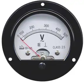
A voltmeter can take many forms, from the classic analog voltmeter with a moving needle to modern instruments like the digital voltmeter (DVM) or the versatile digital multimeter. These tools are essential for measuring electrical values in electronic devices, enabling technicians to measure voltage, current, and resistance with precision and accuracy. While analog units provide quick visual feedback, digital versions deliver more precise measurements across wider voltage ranges, making them indispensable for troubleshooting and maintaining today’s complex electrical systems.
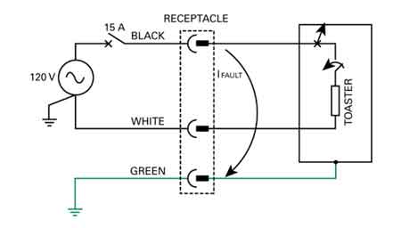
A voltmeter can be tailored to have various full-scale ranges by switching different values of resistance in series with the microammeter, as shown in Fig. 3-6. A voltmeter exhibits high internal resistance because the resistors have large ohmic values. The greater the supply voltage, the larger the internal resistance of the voltmeter because the necessary series resistance increases as the voltage increases. To understand how a voltmeter works, it helps to first review basic electricity, as voltage, current, and resistance form the foundation of all electrical measurements.
Fig 3-6. A simple circuit using a microammeter (tA) to measure DC voltage.
A Voltmeter, whether digital or analog, should have high resistance, and the higher the better. You don't want the meter to draw a lot of current from the power source. (Ideally, it wouldn't draw any current at all.) The power-supply current should go, as much as possible, towards operating whatever circuit or system you want to use, not into getting a meter to tell you the voltage. A voltmeter is commonly used to measure voltage drop across conductors or devices, helping electricians ensure circuits operate efficiently and safely. For quick calculations, a voltage drop calculator provides accurate estimates of conductor losses based on length, size, and current. Understanding the voltage drop formula allows engineers and technicians to apply theoretical principles when designing or troubleshooting electrical systems.
Also, you might not want to keep the voltmeter constantly connected in parallel in the circuit. You may need the voltmeter for testing various circuits. You don't want the behavior of a circuit to be affected the moment you connect or disconnect the voltmeter. The less current a voltmeter draws, the less it affects the behavior of anything that operates from the power supply. Engineers often ask: What is a voltmeter? They use a voltmeter in power system analysis, where accurate voltage readings are crucial for ensuring safety, reliability, and optimal performance.
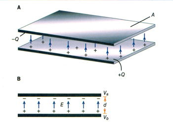
Alternative types of voltmeters use electrostatic deflection, rather than electromagnetic deflection, to produce their readings. Remember that electric fields produce forces, just as magnetic fields do. Therefore, a pair of electrically charged plates attracts or repels each other. An electrostatic type utilizes the attractive force between two plates with opposite electric charges or a large potential difference. A voltmeter is used to measure the potential difference. Figure 3-7 portrays the functional mechanics of an electrostatic meter. It constitutes, in effect, a sensitive, calibrated electroscope. A voltmeter draws essentially no current from the power supply. Nothing but air exists between the plates, and air constitutes a nearly perfect electrical insulator. A properly designed electrostatic meter can measure both AC voltage and DC voltage. However, the meter construction tends to be fragile, and mechanical vibration can influence the reading.
Fig 3-7. Functional drawing of an electrostatic voltmeter movement.
It's always good when a voltmeter has a high internal resistance. The reason for this is that you don't want the voltmeter to draw a significant amount of current from the power source. This current should go, as much as possible, towards working whatever circuit is hooked up to the supply, and not just into getting a reading of the voltage. Additionally, you may not want or need to have the voltmeter constantly connected in the circuit; instead, you might need it for testing various circuits. You don't want the behavior of the circuit to be affected the instant you connect the voltmeter to the supply. The less current a voltmeter draws, the less it will affect the behavior of anything that is working from the power supply.
If you connect an ammeter directly across a source of voltage, a battery, the meter needle will deflect. In fact, a milliammeter needle will probably be "pinned" if you do this with it, and a microammeter might well be wrecked by the force of the needle striking the pin at the top of the scale. For this reason, you should never connect milli-ammeters or micro-ammeters directly across voltage sources. An ammeter, perhaps with a range of 0-10 A, may not deflect to full scale if it is placed across a battery; however, it's still a bad idea to do so, as it will rapidly drain the battery. Some batteries, such as automotive lead-acid cells, can explode under these conditions. This is because all ammeters have low internal resistance. They are designed that way deliberately. They are meant to be connected in series with other parts of a circuit, not right across the power supply. Because voltage is inseparable from current, learning what is current electricity provides deeper insight into why voltmeters are vital diagnostic tools.


But if you place a large resistor in series with an ammeter, and then connect the ammeter across a battery or other type of power supply, you no longer have a short circuit. The ammeter will give an indication that is directly proportional to the voltage of the supply. The smaller the full-scale reading of the ammeter, the larger the resistance needed to get a meaningful indication on the meter. Using a microammeter and a very large resistor in series, it can be devised that draws only a small current from the source.
So, What is a Voltmeter? In summary, a voltmeter is a fundamental instrument for electrical work, allowing professionals and students to accurately measure voltage and understand circuit behaviour. Whether using an analog or digital design, voltmeters and multimeters provide precise insights that support safety, efficiency, and reliable performance in electrical systems.
Related Articles