Basic Electricity – Current, Voltage, Resistance
By William Conklin, Associate Editor
Basic electricity explains how voltage, current, resistance, and power interact in real circuits so professionals can size conductors, prevent overheating, and troubleshoot electrical systems with confidence in practice.
Basic electricity governs whether electrical systems operate safely, efficiently, and within design limits. When fundamentals are misunderstood, the result is not academic error. It is overheated conductors, unstable voltages, nuisance tripping, equipment damage, and preventable safety exposure. Every electrical decision, from wire selection to protective device coordination, is built on these core principles.
In practice, professionals rely on basic electricity to judge how current behaves in a circuit, how resistance limits energy flow, and how voltage reshapes both performance and risk. These relationships define Electrical Units, the behavior of Current Electricity, the limits imposed by Electrical Resistance, and real system outcomes such as Voltage Drop. When these fundamentals are misapplied, design assumptions fail, and safety margins vanish.
Understanding Basic Electricity
Basic electricity also explains why conductors generate magnetic fields, why coils store energy, and why inductors resist rapid changes in current rather than simply allowing current to flow. An inductor is not a shaped wire. It is a control element that governs how quickly current can rise or fall, directly influencing switching behavior, protection performance, and system stability. Even a simple DC electromagnet demonstrates how electrical theory becomes a physical consequence with a switch.
This is why basic electricity is not an introductory topic. It is the structural language of every electrical decision that follows.
Basic Electrical Theory
There are four basic electrical quantities that we need to know:
-
Current
-
Potential Difference (Voltage)
-
Power
-
Resistance
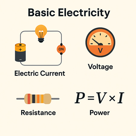
Electrical Current
Current is the rate of flow of electric charge through a conductor. Each electron carries a charge of 1.6 × 10?¹? coulombs, too small to measure individually, so we measure charge in groups called coulombs. When 1 coulomb of charge passes through a point in a circuit per second, the current is 1 ampere (A). Electric current is measured in amperes and is essential to the functioning of all electrical systems.
Potential Difference
Voltage, or potential difference, refers to the energy per unit charge in a circuit. It represents the work each charge can perform. Think of voltage as the electrical pressure that pushes electrons through a conductor. Higher voltage means more potential energy available to do work, such as lighting a bulb or powering a motor. Engineers use the Power Factor Formula to determine how effectively electrical energy is converted into useful work rather than being wasted as reactive losses.
Power in a Circuit
Electrical power is the rate at which energy is used or transferred in a circuit. It can be calculated using the formula:
Power (W) = Voltage (V) × Current (A)
This equation is fundamental in both residential and industrial applications, from estimating energy usage to designing electrical systems.
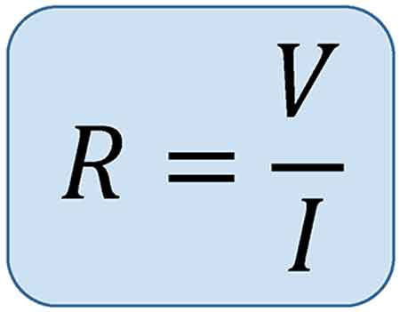
Electrical Resistant Behaviour
Resistance is the opposition to the flow of electric current. It determines how much current will flow for a given voltage. Materials like copper have low resistance and conduct electric power well, while materials like rubber have high resistance and are used as insulators.
Electromagnetic Induction
There’s a reciprocal relationship between electric current and magnetism. When a magnet is moved past a conductor at a right angle, it induces a voltage in the conductor—a principle known as electromagnetic induction. The polarity of the induced voltage depends on the direction and orientation of the magnetic field.
This effect becomes more noticeable when the conductor is coiled. As the north pole of the magnet passes the coil, voltage is induced, and current flows. When the south pole passes, the induced voltage reverses polarity, and the current changes direction. This principle is the foundation of generator operation.
The Generator and the Sine Wave
In an electric generator, coils placed on opposite sides of a rotating magnet generate alternating current (AC). These voltages combine, doubling the output. For example, a 120-volt, 60-Hz generator produces a wave that oscillates between +169.7V and -169.7V.
This wave is called a sine wave because the voltage at any point corresponds to the sine of the magnet’s angle of rotation. The cycle repeats 60 times per second in North America (60 Hz), creating the household AC power we are familiar with.
Forms of Electricity: AC and DC
Basic Electricity exists in two major forms:
-
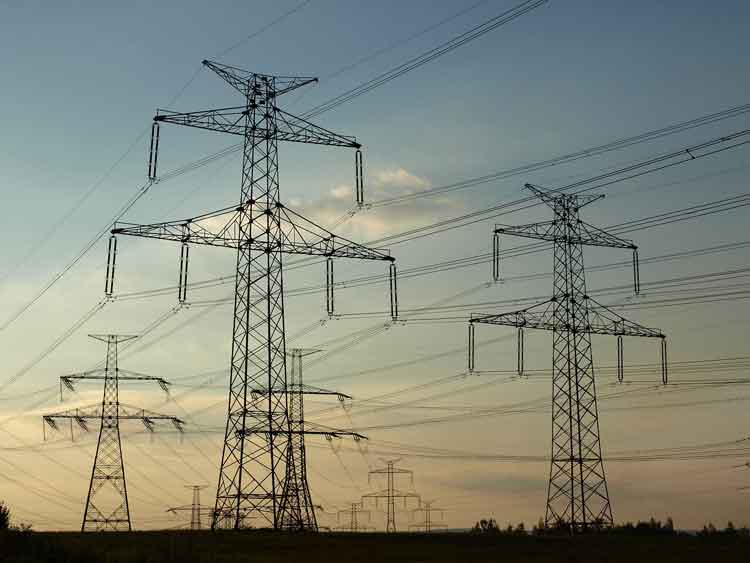
Alternating Current (AC): The direction of current flow alternates regularly. AC electricity is used in power grids because it is easier to transmit over long distances and is compatible with devices such as transformers and capacitors.
-
Direct Current (DC): The current flows steadily in one direction. DC is commonly used inside electronics and battery-powered devices. Unlike AC, the voltage remains constant, making it easy to measure with a DC voltmeter.
AC – Alternating Current
Alternating current is the most common form of basic electricity used in homes, businesses, and utilities. It alternates direction 50–60 times per second, depending on the region. AC is generated by AC generators and is preferred for its ability to easily change voltage levels, making it efficient for transmission over long distances. Sudden dips in power can disrupt equipment — find out what causes voltage sag and how to prevent it.


DC – Direct Current
Direct current flows continuously in one direction. Because its voltage is steady or changes very slowly, it’s easy to measure. It is used in battery-powered systems and internal electronic circuits. Unlike AC, DC cannot be easily stepped up or down in voltage without complex circuitry.
When calculating AC power, engineers use RMS (Root Mean Square) voltage, which gives an effective value comparable to DC. For example, 120V AC RMS is equivalent in power to 120V DC, despite the AC waveform's variations. Direct current behavior is best understood in the context of Current Electricity, where charge flow, polarity, and measurement are examined in practical terms.
Transformers and Induction
Transformers, built using coiled wires around iron cores, rely on electromagnetic induction. When AC flows through the primary coil, it creates a changing magnetic field that induces a voltage in the secondary coil. This allows voltage to be stepped up or down for different uses, such as high-voltage transmission or low-voltage device operation.
Atoms, Electrons, and Electric Charge
To fully grasp electrical energy, it’s essential to understand atomic structure. All matter is made up of atoms, which contain a nucleus of protons (positive) and neutrons (neutral), surrounded by orbiting electrons (negative). The outermost electrons, called valence electrons, can be knocked loose by energy, creating an electric current.
When electrons leave an atom, it becomes positively charged. This movement of charge is the essence of electrical energy. The ability of atoms to gain or lose electrons determines whether a material is a conductor (like copper) or an insulator (like plastic).
Electrical Charge and Attraction
One universal rule in electricity and magnetism is that like charges repel and opposite charges attract. A positively charged object will attract a negatively charged one. This principle governs everything from how circuits function to how magnetic fields interact with conductors. Electrical power relationships are formally defined by Watts Law, which relates voltage, current, and power in a single framework used in system design and load evaluation.
Related Articles