Three Phase Electricity Explained
By Frank Baker, Associate Editor
_1497176406.webp)
Three phase electricity delivers power using three alternating currents that are offset in phase. It provides consistent and efficient energy for industrial, commercial, and high-load applications, improving stability and reducing conductor size.
In an alternating current AC system, power is delivered through a full cycle in which voltage rises, falls, and reverses direction, allowing energy to be transmitted efficiently at higher voltage levels. Unlike single-phase AC power, which depends on a single waveform and often requires a neutral wire to complete the circuit, three-phase systems use a phase alternator to generate multiple waveforms that share the load more evenly.
Understanding How Three-Phase Electricity Works
Three-phase electricity sits at the core of modern power generation, transmission, and distribution. Once electrical demand moves beyond lighting and small appliances, single-phase systems quickly become inefficient and mechanically problematic. Three-phase systems solve this by using three separate alternating currents, each shifted 120 degrees from the others, so power is always being delivered somewhere in the cycle.
This phase offset is why three-phase systems behave so differently from single-phase circuits. Instead of power rising and falling to zero, the combined output remains effectively continuous. Anyone who has watched a large motor struggle on single-phase power understands why this matters. Understanding the distinction between alternating current and direct current also helps clarify why three-phase AC became the global standard rather than a historical curiosity. Understanding the difference between alternating current and direct current is essential to grasping how three-phase systems deliver constant power using offset waveforms.
Understanding the Concept
A three-phase system works because its three sinusoidal waveforms overlap, smoothing out energy delivery. When one phase is approaching its peak, the others are already carrying the load. The result is constant power transfer, not just on paper, but in how equipment actually behaves in the field.
This stability shows up quickly during commissioning and maintenance. Balanced current flow reduces heating, limits vibration, and makes fault conditions easier to diagnose. That is why electricians and engineers pay close attention to phase balance using instruments such as ammeters, especially when troubleshooting motors, panels, or distribution equipment that appears to be running hotter than expected.
In practical terms, three-phase electricity extends equipment life and reduces operating headaches. Large motors start more cleanly, loads run quieter, and protective devices trip less unpredictably when the system is properly balanced.
Since three-phase electrical systems rely heavily on accurate current flow measurement, it’s important to know what ammeters measure and how they help monitor system balance.
A Brief History
Three-phase electricity was not a single invention but a convergence of ideas that emerged in the late nineteenth century. Galileo Ferraris demonstrated rotating magnetic fields in Italy, Nikola Tesla patented polyphase systems in the United States, and Mikhail Dolivo-Dobrovolsky built practical three-phase networks in Europe. Together, their work moved electrical power out of laboratories and into factories and cities.
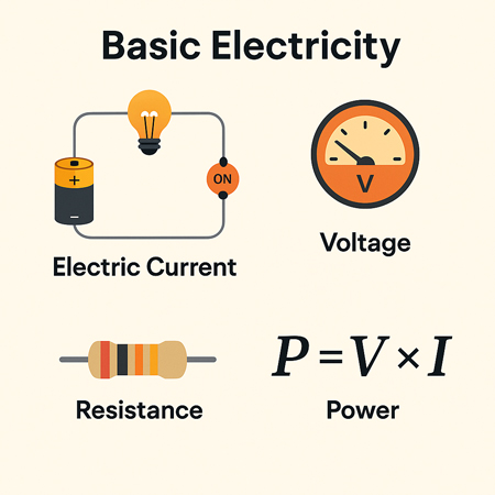
Many of the measurement tools still used today grew alongside these systems. Wattmeters remain essential for understanding real power in three-phase circuits, while Watts Law continues to underpin everyday calculations involving voltage, current, and power. The math may be old, but it has not been replaced.
Engineers use wattmeters to accurately measure real power in three-phase systems, while Watts Law helps calculate the relationships between voltage, current, and power.
Wye and Delta Configurations
Most three-phase systems are wired using either a Wye (Y) or Delta (Δ) configuration, and the choice is rarely arbitrary.
In a wye configuration, this arrangement allows supplying both higher voltage for heavy equipment and lower voltage for standard loads from the same source, which is one of the reasons it is so widely used in commercial and industrial installations.
A Wye connection includes a neutral point, which allows multiple voltage levels from the same supply. This makes it common in commercial buildings where lighting, receptacles, and mechanical loads coexist. It is flexible, but it also introduces the possibility of neutral imbalance if loads are poorly distributed.
Delta systems form a closed loop without a neutral conductor. They are mechanically robust and well-suited to industrial motors, particularly where consistent torque matters more than voltage flexibility. However, they can complicate grounding and fault detection if not designed carefully.
Engineers learn early to respect the √3 relationship between line and phase values. It appears simple in textbooks, but mistakes around this relationship still show up regularly in cable sizing, protection settings, and transformer selection.
Technical Benefits
One reason three-phase systems scale so well is that, under balanced conditions, the phase currents sum to zero. This often eliminates the need for a neutral conductor, reducing copper usage and simplifying installation. Over long runs, those material savings become significant.
Three-phase motors also benefit from physics doing the work for them. The rotating magnetic field is inherent to the supply, not created artificially, which means fewer components, smoother operation, and less wear over time.
Another advantage that is easy to overlook is power consistency. Single-phase power drops to zero twice per cycle, which may not matter for small loads but becomes a real problem for sensitive equipment. Three-phase systems avoid this entirely. In distribution panels, busbars play a critical role in managing this steady flow while keeping connections compact and accessible.

_1497176752-2.webp)
The function of a busbar is especially important in three-phase distribution panels, as it helps manage multiple circuit connections efficiently.
Where and Why It’s Used
Residential buildings rarely need three-phase power, and forcing it into small installations usually creates more complexity than benefit. Beyond that scale, however, three-phase becomes unavoidable. Factories, hospitals, data centers, and large office buildings depend on it for elevators, HVAC systems, production lines, and backup infrastructure.
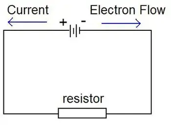
If you're working with three-phase motors or transformers, knowing the role of a conductor and how electrical resistance affects current flow is fundamental to efficient design.
It is increasingly common in electric vehicle charging installations and renewable energy systems, where high-capacity delivery and predictable performance are essential. In these environments, understanding conductor behaviour and the effects of electrical resistance is not academic; it directly affects efficiency, heat buildup, and reliability.
When three-phase service is unavailable, phase converters provide a workable alternative. They are not perfect and introduce limitations of their own, but they allow three-phase equipment to operate when a single-phase supply is the only option. Many commercial three-phase systems operate at medium voltage, and their inherent stability can reduce certain ground fault risks when properly designed and maintained.
Three-phase systems often operate at medium voltage, especially in commercial settings, and their stability can reduce the risks of ground faults.
Voltage Levels and Color Codes
Voltage standards vary by region. In North America, common three-phase systems include 120/208 volts and 277/480 volts. Much of Europe and Asia use 230/400 volts. Color codes differ as well, with red, yellow, and blue common in Europe, and black, red, and blue typical in North America.
These conventions are not cosmetic. They exist to reduce errors during installation, testing, and maintenance, especially when technicians move between jurisdictions.
The Global Standard for Power
Three-phase electricity has endured because it works. It delivers large amounts of power efficiently, scales cleanly, and behaves predictably under load. From heavy industry to modern infrastructure, it remains the backbone of electrical systems worldwide.
Its continued dominance is not a matter of historical inertia. It is the result of physics, economics, and decades of real-world experience converging on a solution that still holds up.
Related Articles
_1497174879.webp)
_1497176752.webp)


