Capacitors in Series Explained
By R.W. Hurst, Editor
Capacitors in series lower the total capacitance but increase voltage handling. This configuration is widely used in electronics, circuit design, and energy storage to balance voltage and improve reliability.
Understanding Capacitors in Series
Capacitors in series describe a circuit configuration in which capacitors are connected end to end, affecting the capacitance and voltage distribution.
They play a critical role in various electronic applications, and understanding their characteristics, advantages, and potential drawbacks is essential for designing and implementing successful circuits. By mastering the concepts of capacitance, voltage distribution, and energy storage, one can leverage capacitors in series to design optimal circuits. To fully understand how capacitors (caps) behave in different setups, it helps to compare Capacitance in Parallel with Capacitance in Series and see how each affects circuit performance.
Capacitors are fundamental components in electronic circuits, with applications ranging from simple timing circuits to sophisticated filtering. This article delves into the intricacies of series-connected caps, highlighting their characteristics, advantages, and potential drawbacks.
To understand capacitors in series, it's essential first to grasp the concept of capacitance, which represents a capacitor's ability to store electric charge. Caps consist of two conductive plates separated by a dielectric material that can store energy when a voltage is applied. The amount of energy stored depends on the capacitance value, voltage rating, and the dielectric material used. Engineers often study Capacitance and its capacitance definition to calculate charge storage and predict how components will interact in series circuits.
When caps are connected in series, their individual capacitances add to the total equivalent capacitance. The series connection is achieved when the positive plate of one capacitor is connected to the negative plate of the subsequent capacitor. This forms a continuous path for current flow, creating a series circuit.
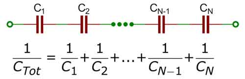
Calculating the total capacitance for capacitors in series is different from parallel capacitors. In a series connection, the reciprocal of the total equivalent capacitance is equal to the sum of the reciprocals of the individual capacitance values. Mathematically, this is represented as:
1/C_total = 1/C1 + 1/C2 + 1/C3 + ... + 1/Cn
Where C_total is the total equivalent capacitance, and C1, C2, C3, ... Cn are the individual capacitance values of the number of caps connected in series.
In a series connection, the electric charge stored in each capacitor is the same. However, the voltage across each capacitor varies depending on its capacitance. According to Kirchhoff's voltage law, the sum of the voltages across individual capacitors equals the applied voltage. Thus, higher capacitance values will result in lower voltage drops, while lower capacitance values will result in higher voltage drops.
There are both advantages and disadvantages to connecting capacitors in series. On the plus side, the series connection's voltage rating increases, allowing the circuit to handle higher voltages without risking damage to the caps. This feature is particularly useful in high-voltage capacitors in series applications. Alongside capacitors, Amperes Law and Biot Savart Law provide deeper insight into the electromagnetic principles that govern current and voltage distribution.
However, there are also drawbacks to this arrangement. The total equivalent capacitance decreases as more capacitors are added in series, potentially limiting the circuit's energy storage capacity. Moreover, in the event of a capacitor failure, the entire series connection is compromised.
Different capacitor types and values can be combined in series, but care must be taken to account for each capacitor's voltage rating and tolerance. For instance, mixing capacitors with different dielectric materials may lead to uneven voltage distribution and reduced overall performance. Since Capacitors are essential to energy storage and timing circuits, learning their behavior in a Capacitors in Series arrangement is key for advanced electronics design.
Determining the total energy stored in a series connection of capacitors involves calculating the energy stored in each capacitor and summing the results. The formula for energy storage in a capacitor is:
E = 0.5 * C * V^2
Where E is the energy stored, C is the capacitance, and V is the voltage across the capacitor. Calculating each capacitor's energy and adding the results can determine the total energy stored in the series connection.
Compared with parallel configurations, the total capacitance increases in parallel connections and decreases in series connections. In parallel, the total capacitance is the sum of the individual capacitance values:
C_total = C1 + C2 + C3 + ... + Cn
A crucial aspect of working with capacitors in series is the distribution of charge. As mentioned earlier, the electric charge stored in each capacitor is the same, but the voltage distribution varies depending on the capacitance values. This characteristic influences the circuit's behaviour and must be considered when designing complex electronic systems. Uneven voltage distribution can affect the entire system's performance, making choosing caps with appropriate capacitance values and voltage ratings for a specific application is vital.
Another important factor to consider is the plate area. In general, caps with larger plate areas have higher capacitance values. Therefore, when connecting capacitors in series, it is essential to evaluate how each capacitor's plate area affects the overall capacitance of the series connection. Understanding these factors will enable engineers and hobbyists to make informed decisions when designing and constructing electronic circuits.
Capacitors in series are versatile and valuable configurations for various electronic applications. By understanding the principles of capacitance, voltage distribution, energy storage, and the influence of dielectric materials, one can harness the full potential of capacitors connected in series.


Additionally, being mindful of this configuration's advantages and disadvantages, and considering the compatibility of different capacitor types and values, will enable the creation of efficient, reliable, and effective electronic circuits. As electronics evolve, they will remain critical in developing innovative devices and systems. A solid foundation in Basic Electricity makes it easier to grasp why capacitors in series lower overall capacitance but increase voltage handling.
Related Articles
_1497153600.webp)
_1497175164.webp)

