Capacitance in Parallel Explained
By R.W. Hurst, Editor
Capacitance in parallel occurs when capacitors are connected side by side, and their values add together. This increases total capacitance, ensures stable voltage, supports efficient charge distribution, and is essential in electronics, energy storage, and reliable circuit design.
A Practical Guide to Capacitance in Parallel
To learn the fundamentals, see what is capacitance, which explains how capacitors store charge, the role of farads, and why this property is essential in circuits and energy storage.
Understanding Parallel Capacitor Behavior
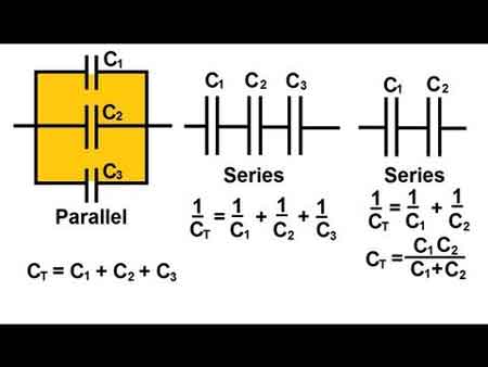
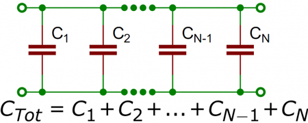
When capacitors are connected in parallel, the effective plate area increases, and the total capacitance is the sum of the individual capacitances. Figure 1 shows a simplified parallel circuit. The total charging current from the source divides at the junction of the parallel branches. To fully understand how capacitors behave in parallel, it helps to revisit the basics of what is a capacitor and how capacitance works in circuits.
Fig. 1 - Simplified parallel circuit.
There is a separate charging current through each branch, allowing each capacitor to store a different charge. Using Kirchhoff’s current law, the sum of all the charging currents is then equal to the total current. The sum of the charges (Q) on the capacitors equals the total charge on them. The voltages (E) across all of the parallel branches are equal. With all of this in mind, a general equation for capacitors in parallel can be determined as:
QT = Q1 + Q2 + Q3
Because Q = CE: CTET = C1E1 + C2E2 + C3E3
Voltages can be factored out because:
ET = E1 + E2 + E3
Leaving us with the equation for capacitors in parallel:
CT = C1 + C2 + C3
Consider the following example:
If C1 = 330μF, C2 = 220μF
Then CT = 330μF + 220μF = 550μF
To calculate the total capacitance in a parallel combination, add the individual capacitors' values. This method is straightforward and differs from series connections, where the reciprocal of each capacitor must be used. The total increases with the number of capacitors added in parallel, making this configuration ideal for applications that require higher capacitance. When designing circuits, understanding how a parallel combination enhances energy storage compared to a series connection is crucial for selecting the optimal number of capacitors to achieve the desired performance. For a detailed breakdown of how capacitance is measured, check out the unit of capacitance to understand farads and their practical conversions.
Since voltage remains constant across parallel capacitors, a firm grasp of what is voltage and its behavior in different configurations is essential.
Capacitance in Alternating Current
If a source of alternating current is substituted for the battery, the capacitor acts quite differently than it does with direct current. When an alternating current is applied in the circuit, the charge on the plates constantly changes. [Figure 2] This means that electricity must flow first from Y clockwise around to X, then from X counterclockwise around to Y, then from Y clockwise around to X, and so on. Although no current flows through the insulator between the plates of the capacitor, it constantly flows in the remainder of the circuit between X and Y. In a circuit in which there is only capacitance, current leads the applied voltage, as contrasted with a circuit in which there is inductance, where the current lags the voltage. Capacitors in AC circuits are deeply influenced by what is alternating current, where the current leads the voltage due to capacitive reactance.
Fig. 2 - Capacitor in an AC circuit.
The parallel connection rule CT = C1 + C2 + C3 reflects the broader principles of resistances in parallel, though capacitance behaves in an additive way instead of being reciprocal.
Capacitive Reactance Xc
The effectiveness of a capacitor in allowing AC to pass depends on the circuit capacitance and the applied frequency. To what degree a capacitor allows an AC flow to pass depends largely upon the capacitive value of the capacitor, given in farads (F). The greater the capacitance, the more electrons, measured in coulombs, are required to charge the capacitor fully. Once the capacitor approaches or reaches full charge, its polarity will oppose the applied voltage, essentially acting as an open circuit.
To further illustrate this characteristic and how it manifests itself in an AC circuit, consider the following:
If a capacitor has a large capacitance, a high-frequency current can flow through it without the capacitor ever reaching full charge. In this case, the capacitor may offer very little resistance to current.
However, the smaller the capacitance, the fewer electrons are required to bring it up to a full charge, and it is more likely that the capacitor will build up enough of an opposing charge to present significant resistance, possibly behaving like an open circuit. Understanding Kirchhoff’s Law helps explain how current divides among parallel capacitors and supports accurate calculations.
Comparison With Series Capacitance
Understanding the difference between series and parallel capacitance is critical for circuit design:
| Configuration | Total Capacitance | Voltage Behavior | Current Behavior |
|---|---|---|---|
| Parallel | Adds directly: CT = C1 + C2 + ... | Same across all components | Divides among branches |
| Series | Inverse sum: 1/CT = 1/C1 + 1/C2 + ... | Divides across components | Same through all components |
-
Parallel is best when you want more capacitance and voltage stability.
-
Series is used when you need a lower total capacitance or to increase voltage tolerance.
To explore how capacitors behave when connected end-to-end, visit capacitance in series, which explains the reciprocal formula and voltage behavior.


Practical Design Considerations
-
Voltage Rating: In parallel, all capacitors share the same voltage. The lowest voltage rating among capacitors determines the safe operating voltage of the group.
-
Physical Size: Adding more capacitors increases board space. Designers must balance performance with space constraints.
-
Energy Storage: Parallel configurations store more energy, making them ideal for power supplies, smoothing circuits, and buffering in audio and RF systems.
Real-world circuit design also requires familiarity with types of capacitors, as their materials and tolerances affect total capacitance and performance.
Real-World Applications of Parallel Capacitors
-
Power Supply Smoothing: Bulk capacitors in parallel stabilize the DC output.
-
Decoupling Noise: Small-value capacitors placed in parallel with larger ones eliminate high-frequency interference.
-
Tuning Circuits: In radio circuits, variable capacitors, when used in parallel with fixed ones, help tune specific frequencies.
For a broader context, you can explore how electrical resistance and reactive power relate to capacitive elements in AC power systems.
Related Articles