Biot-Savart Law Explained
By R.W. Hurst, Editor
Biot-Savart Law describes how electric current produces a magnetic field, helping engineers calculate field strength, direction, and magnetic effects around conductors in electromagnetism.
Understanding Biot-Savart Law: Principles and Applications
The Biot Savart Law sits at the core of classical electromagnetism because it explains how magnetic fields arise from moving electric charges. Named after Jean Baptiste Biot and Félix Savart, the law gave early scientists a practical way to link current flow to magnetic effects in space. It remains valuable today because even simple conductors generate fields that influence nearby circuits, sensors, and devices. The law provides a structured method to determine how strong that field is, how it changes with distance, and how its direction depends on the orientation of the current element. The relationship between electricity and magnetism lies at the heart of the Biot-Savart Law, which shows how moving charges generate magnetic fields.
The idea begins with a small segment of current in a conductor. This tiny piece contributes a small magnetic field, and the total field is the sum of all contributions along the wire. The strength of each contribution increases with current and decreases as the observation point moves farther away. Its direction follows a right hand rule that wraps around the conductor, giving a quick physical picture of the magnetic pattern before any mathematical steps are taken. When working with straight conductors, the field is often written using the permeability constant multiplied by the current, divided by the geometric factors that describe distance and direction. When studying current flow, it helps to compare this law with Ampere’s Law, which is often applied to symmetrical conductors and steady-state conditions.
Biot-Savart Law and Electromagnetism
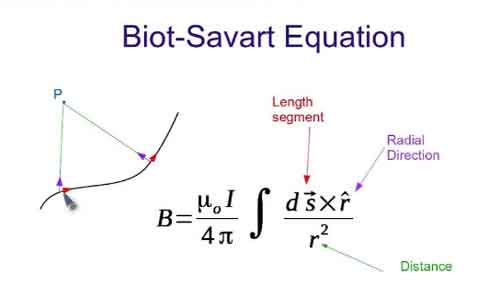
In electromagnetism, the Biot-Savart Law offers a direct route to calculating magnetic fields produced by steady currents. Its mathematical form, dB = mu_0/4pi times the cross product of the current element and the unit direction vector divided by the square of the distance, captures all the important variables in a single compact expression. The cross product sets the orientation of the field, the inverse square term reflects how influence weakens with distance, and the constant sets the scale.
Each component of the formula has physical meaning. The current element represents a short piece of the conductor, the unit vector points to the location where the magnetic field is being evaluated, and the distance determines how much that element contributes. Integrating these contributions across the entire conductor yields the complete magnetic field distribution. This approach is especially valuable when symmetry is limited or the conductor's geometry is irregular. Engineers use it routinely for wires, loops, solenoids, and complex coil shapes where other laws become difficult to apply.
To find the total magnetic field at a point in space due to an entire current distribution, you need to integrate the magnetic field contributions from each infinitesimal current element over the entire current-carrying conductor:
B = ∫dB
The Biot-Savart Law is particularly useful for calculating the magnetic field in cases with complex current configurations or where symmetry is not apparent. In addition, it is often applied in situations where Ampere's Law would be difficult or impossible to use. Common applications include calculating magnetic fields due to straight wires, loops, and solenoids. A foundation in basic electricity concepts makes it easier to understand how current elements combine to produce magnetic fields.
Maxwell's Equations
The Biot-Savart Law fits naturally within Maxwell's broader framework, even though it predates Maxwell’s work by several decades. It can be derived from Ampere’s Law, one of the four Maxwell Equations, which establishes the general link between electric currents and magnetic fields. While Ampere’s Law excels in systems with clear symmetry, the Biot-Savart Law is more flexible because it works with conductors of almost any shape.
The distinction between the two becomes important in practical analysis. Ampere’s Law is ideal for infinite lines, toroids, or solenoids with uniform windings. The Biot-Savart Law handles everything else. The two laws complement each other, providing engineers with both a broad theoretical framework and a versatile computational tool.
Practical Applications
The practical value of the Biot-Savart Law appears across many technologies. Designers of electromagnets, magnetic sensors, and induction-based systems depend on accurate field calculations to ensure proper performance. MRI machines rely on precisely shaped magnetic fields that must remain uniform over a controlled region. Particle accelerators require field calculations that guide charged particles along defined paths. Hard drives and other magnetic storage devices depend on predictable interactions between magnetic fields at microscopic scales.
The law’s adaptability makes it useful for modelling almost any coil geometry, from simple circular loops to toroidal or saddle-shaped designs. It also clarifies how multiple current paths interact, allowing engineers to predict interference or coupling between nearby conductors. When paired with Faraday’s Law, which explains how changing magnetic fields induce voltage, the Biot-Savart Law helps lay the foundation for transformers, generators, and inductive components used throughout power and electronic systems.


The Study of Electromagnetism
A complete understanding of electromagnetism requires attention to both electric and magnetic fields. Electric fields arise from charges and follow Coulomb’s Law, while magnetic fields arise from currents and follow the Biot-Savart Law. Together, they illustrate how static charges and moving charges influence their surroundings.
The mathematics that supports the Biot-Savart Law highlights the role of vector calculus. The cross product describes orientation, the dot product appears in related expressions, and the permeability constant defines how easily a magnetic field forms in free space. These tools allow engineers and scientists to analyze field behaviour in a structured way, whether the goal is simple visualization or complex numerical modelling.
The law remains central to electromagnetic theory because it links physical intuition with mathematical precision. It can explain the magnetic field of a single loop, the field inside a solenoid, the influence of bent conductors, or the combined effect of multiple coils in a device. Its range makes it indispensable from classroom demonstrations to advanced industrial applications.
Ultimately, the Biot-Savart Law continues to support the study and development of technologies that rely on magnetic fields. Whether the task involves generating power, transmitting signals, storing information, or creating highly controlled laboratory environments, the law provides a stable foundation. As research advances and new devices emerge, the Biot-Savart Law will continue to guide the analysis of magnetic behaviour in both familiar and novel settings. For a broader perspective on how energy sources shape our electrical systems, exploring alternative electricity provides useful context.