Capacitors Explained
Capacitors store electrical energy via a dielectric, offering capacitance for filtering, smoothing, and decoupling in AC/DC circuits, RC networks, and power supplies, spanning ceramic, film, and electrolytic types with distinct impedance profiles.
The Science Behind Capacitors
Capacitors for Power Factor Correction
It is desirable to add shunt capacitors in the load area to supply the lagging current component with positive electrons. The cost is frequently justified by the value of circuit and substation capacity released and/or reduction in losses. The installed cost of shunt capacitors is usually lowest on primary distribution systems and in distribution substations. For foundational context, see what a capacitor is to understand its role in reactive power.
The application of shunt capacitors to a distribution feeder produces a uniform voltage boost per unit of length of line, out to its point of application. Therefore, it should be located as far out on the distribution system as practical, close to the loads requiring the kilovars. There are some cases, particularly in underground distribution, where secondary capacitors are economically justified despite their higher cost per kilovar. The placement effectiveness also depends on capacitance characteristics relative to feeder impedance.
The development of low-cost switching equipment for capacitors has enabled correcting the power factor to a high value during peak-load conditions without overcorrection during light-load periods. This enables switched capacitors to be used for supplementary voltage control. Time clocks, temperature, electric charge voltage, current flows, and kilovar controls are common actuators for high-frequency capacitor switching. Utilities typically choose among several types of capacitors to balance switching duty and reliability.
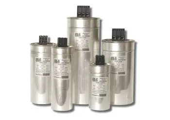
Capacitor Installations
Capacitors for primary systems are available in 50- to 300-kvar single-phase units suitable for pole mounting in banks of 3 to 12 units. Capacitors should be connected to the system through fuses so that a capacitor failure will not jeopardize system reliability or result in violent case rupture. When voltage ratings limit a single unit, engineers connect capacitors in series to distribute stress effectively.
Effect of Shunt Capacitors on Voltage
Proposed permanently connected capacitor applications should be checked to ensure that the voltage for some customers does not rise too high during light-load periods. Switched-capacitor applications should be checked to ensure that switching the capacitor bank on or off will not cause objectionable flicker in the electronics. Selecting appropriate sizes in the standard unit of capacitance helps manage voltage rise and flicker.
Effect of Shunt Capacitors on Losses
The maximum loss reduction on a feeder with distributed load is obtained by locating positively and negatively capacitor banks on the feeder, with the capacitor kilovars equal to twice the load kilovars beyond the point of installation. This principle holds whether one or more capacitor banks are applied to a feeder. To meet kvar targets with modular banks, utilities often add capacitance in parallel so reactive output scales predictably.
Capacitors can be applied at up to 70% of the total kilovar load on the feeder as a single bank, with little sacrifice in the maximum feeder-loss discharge reduction achievable with several capacitor banks.
A rule of thumb for locating a single capacitor bank on a feeder with uniformly distributed loads is that the maximum loss reduction occurs when the bank's kilovars are equal to two-thirds of the feeder's kilovar load. This bank should be located two-thirds of the distance out on the distributed feeder portion for object charging. Deviation of the capacitor bank location from the point of maximum loss reduction by up to 10 per cent of the total feeder length does not appreciably affect the loss benefit. Therefore, in practice, to make the most of the capacitor's loss reduction and voltage benefits, it is best to apply the capacitor bank just beyond the optimum loss-reduction location.
Batteries and capacitors seem similar as they both store and release electrical energy. However, there are crucial differences between them that affect their potential electronic applications, as they function differently depending on the insulator material.
Supercapacitors
A capacitor battery aligns the molecules of a dielectric across an electric field to store energy. A supercapacitor aligns the charge on the electrolyte on either side of an insulator to store a double-layer charge.
Electrolytic capacitors consist of two or more conductive capacitor plates, separated by a dielectric. When an electric current enters the capacitor, the dielectric stops the flow, and a charge builds up, stored in an electric field between the metallic plates. Each capacitor is designed to have a particular capacitance (energy storage). When a capacitor is connected to an external circuit, a current will rapidly discharge. The plate area, separation, and dielectric constant together determine the capacitance and thus the energy density.
In a supercapacitor, there is no dielectric between conducting plates; rather, there is an electrolyte and a thin insulator such as cardboard or paper. When a current is introduced to the supercapacitor, ions build up on either side of the insulator to generate a double layer of charge, regardless of whether the capacitor is charged. Supercapacitors are limited to low voltages and very high capacitance frequencies, as high voltages would break down the electrolyte.
Batteries
There are different types of capacitor batteries, each determining a capacitor's capacitance. Different battery types are distinguished by their chemical makeup. The chemical unit, called the cell, contains three main parts: a positive terminal, the cathode, a negative terminal, the anode, and the electrolyte. Batteries store electric energy, the battery charges and discharges through a chemical reaction that generates a voltage. The stored charge in the battery provides a consistent DC voltage. In rechargeable batteries, the chemical energy that is converted into electricity can be reversed, using external electrical energy to restore the charge of capacitors that store power in the batteries.

_1497176752.webp)