What is a Busbar?
By Howard Williams, Associate Editor
A busbar is a rigid conductor, typically made of copper or aluminum, that serves as a common connection point for multiple circuits within electrical enclosures. It provides a low-resistance path for high current, reduces wiring complexity, and improves thermal and mechanical stability in power distribution systems.
What is a Busbar: Overview
In an electrical system, power is not only controlled by breakers and switches. It is physically guided by the conductors that carry it between those devices. The busbar exists to perform that role with precision, stability, and predictability.
A busbar is a rigid conductor, typically made of copper or aluminum, that serves as a common connection point for multiple circuits within electrical enclosures. Instead of routing individual cables to every protective device and load, engineers use busbars to form a structured backbone that collects incoming power and distributes it throughout the assembly.
Unlike flexible conductors, a busbar is designed to manage current density, heat dissipation, and mechanical forces simultaneously. Its cross-section, surface finish, spacing, and mounting method directly influence temperature rise, voltage drop, and fault-current performance. These physical characteristics determine whether the distribution system operates efficiently or becomes vulnerable to overheating, loose joints, and stress on insulation.
Busbars appear wherever electrical concentration is high, including motor control centers, switchgear lineups, panelboards, and substation equipment. In these environments, the busbar is not merely a conductor. It is the structural pathway that defines how safely and reliably power moves through the system.
Because busbars are designed to continuously carry large amounts of current, their operation is closely tied to the fundamentals of electric current and the way current flows through an electrical system.
Busbars function as rigid conductors, and understanding how they differ from other current-carrying materials is easier when viewed alongside a clear explanation of what is a conductor and how conductive materials behave under load.
How Busbars Function in Practice
In operation, a busbar acts as a common junction. Incoming feeders connect to it, and outgoing connections branch to circuit breakers, disconnects, or other equipment. Because all of these connections share the same conductive mass, current distribution remains stable and predictable.
The large surface area reduces current density, thereby lowering resistive losses and heat. In real installations, this also simplifies troubleshooting. A well-laid-out busbar system makes it easier to see where power enters, how it is divided, and which downstream circuits are affected during a fault.
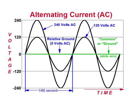
Busbars may be bare, insulated, or fully enclosed. In many panels, they sit behind grounded metal barriers or are positioned out of normal reach. In higher-energy environments, insulation and enclosure design play a significant role in both personnel safety and arc-fault mitigation. In many commercial and industrial installations, busbars are used to distribute three-phase electricity, where balanced loads and stable voltage are critical to system performance.
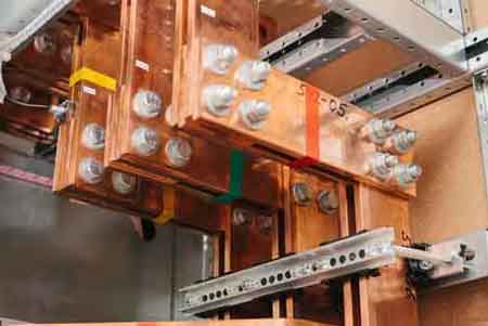
Real-world Installations
In real-world installations, busbars in electrical systems are used wherever reliable electric power distribution depends on a stable, low-resistance path rather than bundles of cable. An electrical busbar is typically formed as a metallic strip or bar, sized so its cross sectional area supports the required carrying capacity without excessive heat generation or power loss.
When designed correctly, the geometry and material choice allow current to flow with minimal energy loss, even under continuous load. Engineers also account for thermal expansion, since temperature changes can affect joint integrity and long-term reliability if movement is restricted. These factors explain why busbars appear in specific applications such as switchgear, substations, and large panels, where predictable performance matters more than flexibility.
Materials and Construction Choices
Copper remains the most common busbar material due to its excellent conductivity and mechanical strength. It performs well in compact assemblies where space is limited and heat dissipation matters. Aluminum busbars, while less conductive, offer weight and cost advantages and are widely used in large distribution systems and bus duct assemblies.
Construction varies with application. Some busbars are solid rectangular bars, especially in low-voltage and medium-current systems. Others are tubular or laminated, designs that help manage electromagnetic forces and heat in higher-current environments. Laminated busbars are often found in power electronics and UPS systems, where tight spacing and controlled impedance are important.
Busbar Types and Characteristics
| Attribute | Copper Busbar | Aluminum Busbar | Laminated Busbar |
|---|---|---|---|
| Conductivity | Excellent (≈100% IACS) | Good (≈61% IACS) | Varies (depends on internal conductor materials) |
| Weight | Heavy | Lightweight | Moderate |
| Cost | Higher | Lower | Higher (due to fabrication complexity) |
| Heat Dissipation | Excellent | Good | Excellent (designed to reduce hot spots) |
| Applications | Switchgear, substations, panels | Bus ducts, high-rise buildings | Compact power modules, UPS, power electronics |
| Mechanical Strength | High | Moderate | Moderate to High |
| Corrosion Resistance | High (especially tinned copper) | Requires anodizing/coating | Depends on encapsulation |
| Ease of Fabrication | Good | Excellent | Complex |
Why Busbars Are Used Instead of Cables
From a design standpoint, busbars reduce complexity. Fewer terminations mean fewer failure points. Mechanical rigidity improves reliability under thermal cycling and fault conditions. For maintenance crews, a busbar-based layout is often easier to inspect than bundles of large conductors.
There is also a safety dimension. Properly designed busbar systems provide clear separation between energized components and working space. When faults occur, predictable current paths and secure mounting reduce the likelihood that conductors will move violently under electromagnetic forces.
Busbars in Distribution Equipment
Busbars are integral to electrical panels, switchgear, and distribution boards. In commercial buildings, they form the backbone of panelboards that divide incoming service into branch circuits. In industrial settings, they carry power through switchgear lineups that control and protect large motors, drives, and process equipment.
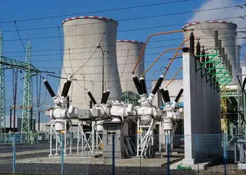
At the utility level, busbars connect transformers, breakers, and feeders within substations. Their layout reflects both electrical requirements and operational priorities, such as isolation, redundancy, and maintenance access. Busbars are commonly used in transformer connections, serving as an essential interface between distribution equipment and devices such as 3 phase transformers.

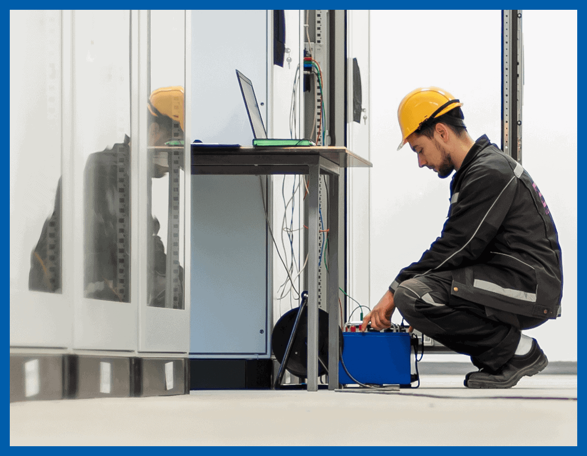
Installation and Ongoing Care
Installing a busbar system begins with load analysis. Current ratings, fault levels, and thermal considerations determine size and spacing. Connections are typically bolted or clamped, with careful attention paid to contact pressure and surface preparation.
Over time, inspection matters. Loose joints, corrosion, and contamination increase resistance and heat. In practice, many busbar failures trace back to neglected connections rather than conductor capacity. Regular visual checks and torque verification go a long way toward preventing larger problems. Voltage considerations also shape busbar design, particularly in systems where managing voltage drop is necessary to maintain efficiency and prevent overheating.
Safety and Fault Risk
Because busbars often carry high energy, accidental contact can be severe. Electrical shock, burns, and equipment damage are real risks if guarding and isolation are inadequate. Short circuits involving busbars can escalate quickly, producing intense heat and mechanical forces.
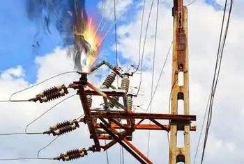
Arc flash is a particular concern. A fault involving a busbar can release enormous energy in a fraction of a second. Proper spacing, insulation, enclosure design, and maintenance all reduce the likelihood of such events. In field experience, overloaded or poorly maintained busbars are far more likely to be involved in arc-related incidents than properly rated and protected systems. When faults occur, a damaged or overloaded busbar can become the origin point of an electrical short circuit, which is why spacing, insulation, and maintenance are so important.
Final Perspective
Busbars are not complex devices, but they are foundational. Their design influences system reliability, safety, and maintainability more than many higher-profile components. When they are sized correctly, installed thoughtfully, and maintained consistently, they quietly do their job for decades, delivering power where it's needed without drawing attention to themselves.