What is Power Factor? Understanding Electrical Efficiency
By R.W. Hurst, Editor
Power factor describes how efficiently electrical power is used in AC systems by comparing real power to apparent power. It explains reactive power, phase angle, and why a poor power factor (PF) increases losses, demand charges, and equipment stress.
What is Power Factor Explained
In alternating current systems, not all supplied electrical power is converted into useful work. Some energy circulates between the source and the load, supporting magnetic and electric fields without directly producing output. Power factor describes how effectively an electrical system converts supplied electricity into usable energy.
Power Quality Analysis Training
Inductive loads, such as motors and variable speed drives, are a common cause of poor power factor. This inefficiency can lead to higher electric bills, particularly for industrial customers, because utilities often base demand charges on kVA rather than just on kW. To correct a poor power factor, capacitor banks are often installed to offset the inductive reactive power, reducing wasted energy and improving system efficiency.
A poor power factor can lead to higher electricity bills, especially for industrial customers who face demand charges based on kVA. Utilities must supply both the real and reactive components of systems, which you can learn more about in our Apparent Power Formula: Definition, Calculation, and Examples guide. To correct PF issues, capacitor banks are often installed to offset inductive effects and bring the system closer to unity power factor.
Request a Free Power Quality Training Quotation
Understanding Power Factor in Electrical Systems
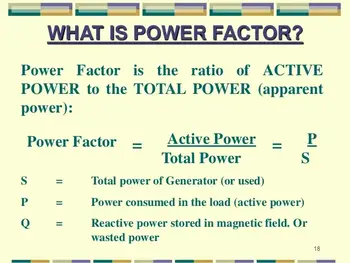
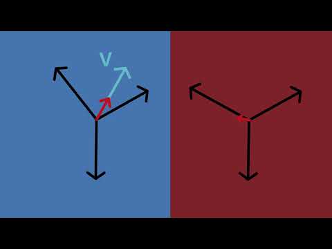
Power factor is the ratio of real power to apparent power in an electrical system. It indicates how efficiently electricity is being used and how closely current and voltage are aligned. When voltage and current are in phase, nearly all supplied power performs useful work. As they drift out of phase, efficiency declines. Their effect on system stability is discussed in our Power Quality and Harmonics guide.
A low power factor means a greater portion of the supplied energy exists as reactive power. This does not produce work but still loads conductors, transformers, and generators. As a result, electrical systems must be sized larger than necessary, increasing operating costs and reducing overall efficiency. See our article on Lagging Power Factor and How to Correct It for a detailed discussion.
PF is a measure of how effectively electrical energy is converted into useful work in AC systems. It compares real power and reactive power, showing how efficiently current is being used to perform work. In facilities with large electric motors, this factor is a measure of how much supplied electricity actually produces mechanical output versus how much circulates without doing useful work.
Why Power Factor Matters
A poor power factor increases current for the same amount of useful energy. This leads to higher conductor losses, greater voltage drop, and additional heating in electrical equipment. Utilities must supply both real and reactive power, which is why many commercial and industrial customers face demand charges based on apparent power rather than kilowatts alone. Explore how it’s calculated in our article on Reactive Power Formula in AC Circuits.
Inductive loads are the most common cause of low power factor. Motors, transformers, and variable-frequency drives require reactive power to generate magnetic fields. Without correction, these loads pull current that does not directly contribute to useful output.
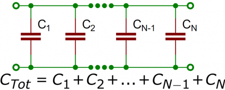
To offset this effect, capacitor banks are often installed to supply leading reactive power locally. This reduces the reactive demand on the utility, improves efficiency, and brings the system closer to a unity power factor.
If you want to calculate power factor quickly, check out our simple How to Calculate Power Factor guide.
The Relationship Between Voltage and Current
Power factor also reflects the timing relationship between voltage and current waveforms. When current lags voltage, the system has a lagging power factor, which is typical of motor-driven installations. When the current leads the voltage, the system has a leading power factor, which can occur in systems with excessive capacitive correction or certain lighting technologies.
In modern facilities, non-linear loads such as electronic drives and switched-mode electrical supplies further complicate PF by distorting the current waveform. Even when the displacement power factor is good, harmonic distortion can reduce overall system efficiency and stability.
Real, Reactive, and Apparent Power
Power factor can be understood by separating electrical energy into three components.
Real power, measured in watts, performs actual work such as turning motors or producing heat. Reactive power, measured in VARs, sustains magnetic and electric fields but does not create output. Apparent power, measured in volt-amperes, is the total energy the system must deliver.
These components form a right-triangle relationship. Real power represents the useful portion, reactive power represents the non-working portion, and apparent power is the total effort required from the supply. As reactive power increases, apparent power rises while real output remains unchanged, lowering the power factor.
The Power Factor Formula
Power factor is calculated using a simple ratio:
Power Factor = Real Power ÷ Apparent Power
A value of 1.0 represents perfect efficiency, where nearly all supplied energy performs useful work. Most utilities consider values above 0.9 acceptable.
In electrical terms, this means the PF approaches 1.0, the ideal scenario in which almost no energy is wasted. For more real-world examples, we provide further explanations in Power Factor Leading vs. Lagging

If your facility has poor power factor, adding a Power Factor Correction Capacitor can make a significant difference.
Causes of Low Power Factor
Low power factor is commonly caused by inductive equipment operating continuously or under light load. Motors running below rated capacity, transformers energized without load, and older lighting systems all contribute to increased reactive power demand.
Non-linear loads introduce additional complexity by distorting current waveforms. These distortions increase losses, reduce available capacity, and may require harmonic mitigation alongside power factor correction.
Simple How-to: Correcting Power Factor
Power factor correction is typically achieved by supplying reactive power locally rather than drawing it from the utility. Capacitor banks are the most common solution, reducing current flow and improving voltage stability. In larger installations, synchronous condensers or advanced control systems provide dynamic correction as loads vary.
Improving power factor reduces electrical losses, stabilizes voltage, extends equipment life, and lowers utility charges. It also frees system capacity, allowing existing infrastructure to support additional loads without upgrades.
Industries Where Power Factor Correction Matters
Industries that operate heavy machinery, large motors, or lighting banks often struggle with low PF.
That is because manufacturing facilities, data centers, hospitals, water treatment plants, and large commercial buildings all rely on equipment that can degrade power factor. In these environments, managing reactive power is essential for maintaining reliability, minimizing downtime, and controlling operating costs.
Facilities that actively monitor PQ and correct poor power factor experience improved system performance and reduced strain on internal equipment and the utility grid.
Facilities interested in monitoring their system health can benefit from tools like a Power Quality Analyzer Explained. Proper correction reduces wasted energy, prevents overheating, and extends the equipment's lifespan.
Power factor management is especially important for utilities and high-demand commercial sites, where poor PF can impact both Quality of Electricity and system reliability.
Related Articles