Substation Grounding - Ensuring Electrical Safety
By Frank Baker, Technical Editor
Substation Relay Protection Training
Our customized live online or in‑person group training can be delivered to your staff at your location.
- Live Online
- 12 hours Instructor-led
- Group Training Available
Download Our OSHA FS3529 Fact Sheet – Lockout/Tagout Safety Procedures
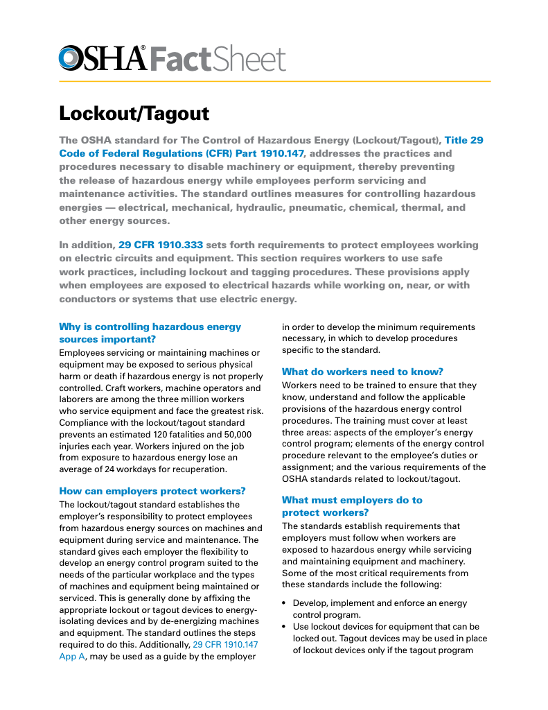
- Learn how to disable machines and isolate energy sources safely
- Follow OSHA guidelines for developing energy control programs
- Protect workers with proper lockout devices and annual inspections
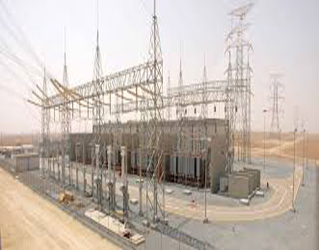
Substation grounding is the engineered network of conductors and electrodes that safely dissipates fault current into the earth, stabilizes voltage reference, and protects personnel and equipment inside high-energy electrical substations.
Because substations concentrate large fault levels within confined physical space, grounding is not a secondary safety feature. It is the structural system that determines how electrical energy behaves during abnormal events. The same principles that govern general electrical grounding apply here, but the consequences of error are far greater.
In practical terms, substation grounding controls step voltage, touch voltage, and fault current return paths so that protective devices can operate predictably and personnel exposure remains within survivable limits.
Why Substation Grounding Controls Safety Outcomes
A properly designed substation grounding network ensures that all exposed conductive surfaces remain at nearly the same electrical potential during fault conditions. This equalization prevents dangerous voltage gradients across walking surfaces, steel structures, and operating equipment.
Without this controlled reference, fault energy migrates unpredictably through soil, foundations, metallic pathways, and human contact points. The result is not only shock risk, but also insulation stress, relay miscoordination, and structural damage.
Electrical Transformer Maintenance Training
Substation Maintenance Training
Request a Free Training Quotation
Grounding System Architecture and Code Context
Substation grounding functions within a broader grounding system architecture that organizes reference points, bonding continuity, and fault current return paths into a unified electrical structure.
Regulatory expectations for this behavior are defined by the electrical grounding code, with jurisdictional interpretation clarified through the CSA and NEC grounding and bonding comparison. These standards exist to ensure grounding performance under real fault conditions, not merely to prescribe materials.
Bonding continuity is essential to this performance. Without bonding, grounding cannot equalize potential across structures. The interaction between these two functions is explained in how grounding and bonding work together, where conductive continuity allows grounding to operate as a system rather than as isolated components.
FREE EF Electrical Training Catalog
Download our FREE Electrical Training Catalog and explore a full range of expert-led electrical training courses.

- Live online and in-person courses available
- Real-time instruction with Q&A from industry experts
- Flexible scheduling for your convenience
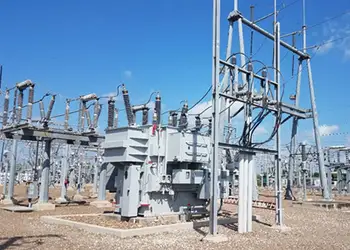
Fault Current Paths and Earth Interface
Fault current follows the grounding electrode conductor that connects the electrodes to the system reference to maintain a stable, predictable return path. The physical earth interface is formed by grounding electrodes that make contact with the soil, and their placement and depth directly influence resistance and energy dissipation.
In many substations, fault current magnitude is intentionally limited using neutral grounding resistors. These devices reduce arc energy, protect insulation systems, and allow protective relays to detect faults without subjecting equipment to destructive current levels.
Relationship to Generator and Transformer Grounding
Substation grounding cannot be separated from equipment grounding behavior. Generator installations follow principles described in grounding a generator, while transformer neutral reference and fault behavior are governed by transformer grounding practices.
The spatial relationships among grids, neutrals, and conductors are illustrated in the transformer grounding diagram, which shows how grounding elements interact in real installations.
Soil Conditions and Ground Grid Performance
Soil resistivity testing determines how effectively a substation grounding system can dissipate fault energy. High-resistivity soils require expanded grids, deeper electrodes, or treatment methods to achieve acceptable resistance values. Without these adjustments, even well-designed conductor networks may fail to protect personnel from hazardous potentials.
When grounding is poorly executed, faults migrate, voltage gradients increase, protective devices misoperate, and insulation stress accumulates. When grounding is properly engineered, faults remain contained, predictable, and survivable.
Substation Grounding as a Design Discipline
Substation grounding is not a construction detail. It is a design discipline that determines whether a substation behaves as a controlled electrical system or as an uncontrolled energy source during abnormal events.
In modern power systems, where safety, reliability, and regulatory accountability are inseparable, substation grounding remains one of the most important structural protections built into the electrical grid.
Related Articles
