Electricity Supply And Demand Balance
_1497174704.webp)
Electricity supply covers generation, transmission, distribution, grid infrastructure, voltage regulation, frequency control, power quality, protection, SCADA, and load management to ensure reliable energy delivery to industrial, commercial, and residential loads.
Electricity Supply Explained
What Is Electricity Supply?
Electricity Supply is a complex balanced system of electric power generation and real time customer demand. Production (supply) and consumption (demand) dictate electricity pricing in the United States and Canada. For a regional view, the analysis at Electricity Demand in Canada highlights how seasonal peaks and resource availability shape prices.
Where does the term "electricity supply" originate? How does that supply move from one point to another? These are most important questions to ask when you want to understand the electric power industry.
If you're new to the vocabulary, the concise glossary at Electricity Terms can clarify definitions used throughout the industry.
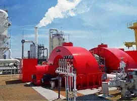
The first thing to know is that electric power is generated in the United States and Canada in power plants which house electrical generators. Then, power is transported (transmission and distriubtution) through the power grid to the customer. This complex network of transmission lines delivers power to industrial, commercial, institutional and residential customers. For a step-by-step overview of system operations, Electricity: How It Works explains generation, transmission, and distribution in practical detail.
In the electricity industry, transmission and distribution wires do the work of transporting power to satisfy electricity demand during real time peak demand. This is the job of the electricity market. The natural gas and fossil fuels industry works in the same way. These lines run from generating station to substations (sometimes over great distances, like in the case of British Columbia and Manitoba where generation is in the far north and the consumption is in the south. This is where the voltage is reduced for local consumption. Substations are usually located close to where the electricity is consumed.
For background on core power concepts, the primer at Electricity Power connects voltage, current, and load to real-world grid behavior.
The various prices of electricity depends on the electricity supply mix and the energy efficiency of the customer. Electricity energy supply is usually measured in terawatt hours.
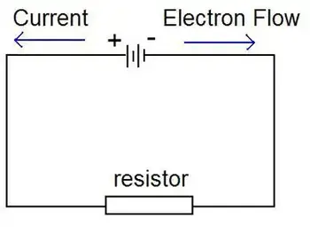
The system design is of three-phase alternating current electrical generation and distribution, which was invented by Nikola Tesla in the 19th century. He considered that 60 Hz was the best frequency for alternating current (AC) power generating Electricity Supply. He preferred 240 V, which was claimed to be better for long supply lines. Thomas Edison developed direct current (DC) systems at 110 V and this was claimed to be safer. For more information about the early battles between proponents of AC and DC supply systems see War of Currents. For foundational fundamentals beyond this history, the overview at What Is Electricity clarifies the principles common to both AC and DC systems.
The German company AEG built the first European generating facility to run at 50 Hz, allegedly because the number 60 did not fit into the numerical unit sequence of 1, 2, 5…. At that time, AEG had a virtual monopoly and their standard spread to the rest of the continent. In Britain, differing frequencies (including 25 Hz 40 Hz and DC) proliferated, and the 50 Hz standard was established only after World War II.
To see how frequency standards interact with generation and end-use performance, the explainer at How Electricity Works ties design choices to everyday operation.
Originally much of Europe was 110 V too, just like the Japanese and the US system today. It was deemed necessary to increase the necessary voltage to draw more electrical power with reduced energy loss and voltage drop from the same copper wire diameter.
The choice of utilization voltage is governed more by tradition than by optimization of the distribution system. In theory, a 240 V distribution system will use less conductor material to deliver a given quantity of power. Incandescent lamps for 120 V systems are more efficient and rugged than 240 V lamps, while large heating appliances can use smaller conductors at 240 V for the same output rating. Practically speaking, few household appliances use anything like the full capacity of the outlet to which they are connected. Minimum wire sizes for hand-held or portable equipment is usually restricted by the mechanical strength of the conductors. One may observe that both 240 V system countries and 120 V system countries have extensive penetration of electrical appliances in homes. National electrical codes prescribe wiring methods intended to minimize the risk of electric shock or fire. For household applications, home electricity basics show how these voltage considerations affect outlets, circuits, and safety practices.
Areas using (approximately) 120V allow different combinations of voltage, suitable for use by a variety of classes of electrical equipment.