What is Impedance? Explained
By William Conklin, Associate Editor
Impedance is the total opposition a circuit presents to alternating current, combining resistance and reactance to control how voltage, current, and power behave in AC systems. It is measured in ohms and varies with frequency, component type, and circuit design.
When impedance is misunderstood or ignored, circuits do not behave as expected. Voltage drops appear where they should not, currents shift out of phase, protective devices respond unpredictably, and power delivery becomes inefficient or unstable. In real installations, this is not an academic issue. It shows up as overheating conductors, mis-sized equipment, poor power factor, nuisance tripping, and distorted waveforms that shorten equipment life.
Impedance also determines critical design and troubleshooting decisions. It affects transformer loading, motor starting performance, cable sizing, fault current levels, and harmonic behavior. Engineers and electricians rely on impedance to predict how a system will respond before it is energized. If the impedance model is wrong, the entire analysis that follows is built on a false assumption.
What Is Impedance?
In alternating current systems, electrical behavior is shaped not only by resistance, but by how inductance and capacitance interact with changing current. Impedance is the combined effect of these influences. It describes how an AC circuit resists, stores, and releases energy as voltage reverses direction, and it ultimately determines how the circuit responds to frequency, load conditions, and system configuration.
Understanding Impedance in AC Circuits
Understanding impedance (Z) is essential for anyone working with AC circuits. It influences how electrical energy flows, how efficiently components interact, and how systems handle varying frequencies. To understand how impedance interacts with voltage, explore our explanation of what is voltage and how it affects current flow in electrical circuits.
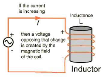
Electrical resistance limits current by converting electrical energy into heat. Reactance stores and releases energy through magnetic fields in inductors and electric fields in capacitors. Together, they determine how much current flows for a given applied voltage and how voltage and current vary over time.
Impedance plays a central role in AC circuit analysis because it explains why current does not always rise and fall in step with voltage. This phase difference affects power transfer, efficiency, and system stability, making impedance essential for design and troubleshooting. In AC systems, the behavior of inductors is described by inductance, which directly contributes to the reactive part of impedance.
How Impedance Is Defined Mathematically
Impedance is defined using the relationship:
Z = V ÷ I
Here, Z is measured in ohms, V is voltage, and I is current. This equation extends Ohm’s Law from DC circuits into AC systems by accounting for frequency-dependent effects.
In practice, impedance is treated as a complex quantity:
Z = R + jX
In this form, R represents resistance, and X represents reactance. The imaginary unit j indicates that reactance causes a phase shift between voltage and current. This representation allows engineers to calculate both the impedance magnitude and the phase angle between voltage and current. Capacitors also play a key role, and understanding capacitance is essential to see how impedance decreases at higher frequencies.
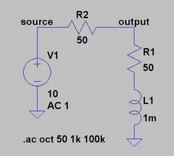
Frequency, Phase Angle, and Reactance
Unlike resistance, impedance depends on frequency. Inductive reactance increases with frequency, while capacitive reactance decreases. This means the same circuit can behave very differently at different frequencies.
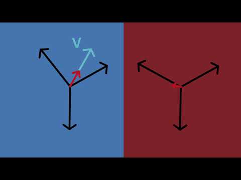
As reactance changes, so does the phase relationship between voltage and current. In inductive circuits, current lags voltage. In capacitive circuits, current leads voltage. These phase shifts directly affect power flow and must be considered when analyzing AC systems, particularly those with harmonics or variable-frequency signals. Learn how resistance contributes to impedance by reviewing what is electrical resistance and how it differs from reactance in AC systems.
Why Impedance Matters in Real Systems
Impedance affects how energy is transferred and how systems perform under load. In audio equipment, proper impedance matching between amplifiers and speakers ensures efficient power transfer and clear sound. In radio frequency systems, matching impedance minimizes reflections and signal loss along transmission lines.
In power systems, impedance influences fault current levels, voltage regulation, and harmonic behavior. Engineers rely on impedance values to size equipment, evaluate short-circuit conditions, and maintain power quality across networks.
For insights into the capacitive elements of impedance, see what is a capacitor and how it stores energy in electric fields.
Impedance in Power and Transformer Systems
Most power system impedance is inductive at the fundamental frequency. Engineers often use short-circuit reactance as a practical representation when detailed phase data is unavailable. This approach is generally accurate for fault studies and load flow analysis.
Transformer impedance, usually expressed as a percentage on the nameplate, accounts for most of the total system impedance in many industrial installations. As frequency increases, resistance effects such as skin effect and eddy-current losses become more significant, helping to dampen resonance in harmonic conditions.
Harmonic Considerations
One common mistake in power quality and harmonic analysis is neglecting to adjust reactance for frequency. The reactance at the h-th harmonic is determined from the fundamental reactance X1 by:
Where h is the harmonic number, and X1 is the fundamental reactance magnitude. (For capacitive branches specifically: XC,h = XC,1 / h, while inductive branches scale as XL,h = h × XL,1.)
In many power systems, resistance remains nearly unchanged up to the ninth harmonic. However, at higher frequencies, skin effect increases the conductor resistance, and transformer eddy-current losses further influence the apparent resistance. These factors affect resonance conditions and can alter predictions of harmonic distortion.


Neglecting resistance generally yields a conservative, higher prediction of distortion. But when transformer effects dominate system behaviour, resistance should be modelled more carefully. Impedance matching is especially important in such cases to ensure stability and avoid resonance issues in AC power systems. The impact of impedance extends to system-level issues, such as harmonic distortion, which can compromise stability and power quality if not properly managed.
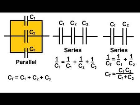
Calculating Total Impedance
Total impedance depends on how components are connected. In series circuits, resistance and reactance combine according to their magnitudes and phase relationships. In parallel circuits, impedance is governed by reciprocal relationships that can amplify even small modelling errors.
When impedance is miscalculated, current flow, voltage drop, and equipment loading are all misjudged at once. The result is not just inefficiency, but also unstable operation, incorrect protective assumptions, and compensation systems that address symptoms rather than causes.
These impedance calculations still follow the logic of Ohm’s Law but are adapted for AC circuits both resistance and reactance shape the outcome. By combining these components correctly, engineers can anticipate circuit behaviour rather than discovering problems after installation. This is why calculating impedance remains a crucial part of power system analysis, where accurate models determine current flow, voltage stability, and fault levels.
Related Articles