Difference between AC and DC
By R.W. Hurst, Editor
The difference between AC and DC explains how alternating current and direct current flow, how voltage and frequency behave, and why AC dominates power transmission while DC is used in electronics, batteries, and renewable energy systems.
Understanding the Difference Between AC and DC
The difference between AC and DC electrical currents is crucial to understanding their unique characteristics and diverse applications. By examining the electron flow, voltage variation, power transmission, and safety implications of each current type, we can better appreciate the complex electrical systems that power our daily lives. This comprehensive article offers a deeper understanding of the fundamental distinctions between AC and DC currents, highlighting their significance in electrical systems. For foundational context, see a concise electricity definition that clearly frames these distinctions.
Alternating Current
AC (alternating current) and DC (direct current) differ fundamentally in the flow of electrons. In an alternating current, the flow of electrons periodically reverses direction, following a sinusoidal waveform. The waveform is described by the formula V(t) = Vm * sin(2 * π * f * t), where Vm is the maximum voltage, f is the frequency, and t is time. On the other hand, in direct current, the flow of electrons is constant and unidirectional, resulting in a steady voltage. For a deeper explanation of sinusoidal behavior, consult our alternating current article to connect theory with practice.
What is AC electrical current, and how is it measured?
AC (alternating current) is an electrical current in which the flow of electrons periodically reverses direction. Unlike direct current (DC), where the electrons flow in a single, constant direction, alternating current alternates between positive and negative values following a sinusoidal waveform.
AC electrical current is measured in several ways:
Amplitude: The maximum value of the current reached during each cycle is called the amplitude. This is the peak value of the sinusoidal waveform and is typically measured in amperes (A).
RMS (Root Mean Square) value: The RMS value is a more practical measurement representing the AC current's effective value. The equivalent DC value would produce the same amount of power as the AC current. To calculate the RMS value of an AC current, you can use the formula I_RMS = I_peak / √2, where I_peak is the peak amplitude of the current.
Frequency: The frequency of an AC current refers to the number of cycles it undergoes per second. It is typically measured in hertz (Hz). In most countries, the standard frequency for AC power systems is either 50 Hz or 60 Hz.
Phase: In AC circuits, multiple currents or voltages may exist with the same frequency but different phase angles. The phase angle is the relative position of the waveform in a complete cycle, measured in degrees (°) or radians. Therefore, it is essential to consider the phase when dealing with multiple AC sources, as it can affect the overall performance of an electrical system.
These measurements are essential for characterizing and analyzing AC electrical currents, allowing engineers and technicians to understand their properties and optimize their use in various applications. For newcomers, our basic electricity primer can reinforce these concepts before moving to advanced analysis.
Direct Current
Two primary types of current dominate the world of electricity: alternating current (AC) and direct current (DC). To understand the difference, we need to explore their unique characteristics, applications, and the principles behind their operation. This comprehensive guide will delve into the details of each electrical current, providing examples and formulas for greater clarity. A broader primer on charge flow is available in this overview of current electricity for readers building fundamentals.
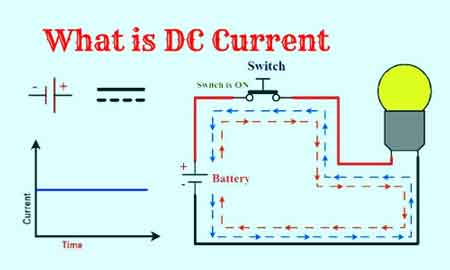
What is DC electrical current, and how is it measured?
DC (direct current) is a type of electrical current where the flow of electrons is constant and unidirectional. Unlike AC (alternating current), which periodically reverses the direction of electron flow, direct current maintains a consistent flow of electrons from the negative to the positive terminal of a power source. A quick reference on terminology is available in this DC current guide for consistent notation across texts.
DC electrical current is typically measured in a few ways:
Amperes (A): The most common unit of measure for DC current is the ampere (A). An ampere represents the rate of flow of electric charge through a conductor, which remains constant over time in DC. Ammeters or multimeters are typically used to measure DC current in a circuit.
Voltage (V): Voltage is the electrical potential difference between two points in a circuit. In DC circuits, the voltage remains constant over time, providing a stable, predictable power source. The voltage across a power source or components in a DC circuit can be measured using a voltmeter or a multimeter.
Power (W): Power is the rate at which electrical energy is transferred in a circuit. In a DC circuit, power can be calculated using the formula P = V * I, where P is power, V is voltage, and I is current. Power can also be measured directly using specialized equipment, such as wattmeters.
Resistance (Ω): Resistance is the opposition a conductor offers to the flow of electric current. In a DC circuit, the relationship between voltage, current, and resistance is described by Ohm's Law: V = I × R, where V is voltage, I is current, and R is resistance. Resistance can be measured using an ohmmeter or a multimeter with a resistance measurement function.


These measurements are essential for characterizing and analyzing DC electrical currents, enabling engineers and technicians to understand their properties and optimize their use across applications such as batteries, solar panels, and electronic devices. For additional background and historical context, see this direct current explainer covering uses and standards.
Voltage Variation
Voltage variation is a key distinction between AC and DC currents. In an AC system, the voltage continuously varies, oscillating between positive and negative values in a sinusoidal waveform. In contrast, DC voltage remains constant, providing a stable, predictable power source essential to many electrical devices.
Power transmission is another area where AC and DC differ significantly. Alternating current is primarily used for transmitting electricity over long distances because it can be stepped up or stepped down using transformers. These transformers can adjust the voltage levels, enabling the efficient transmission of electrical energy from power plants to households and businesses. The transmission efficiency is enhanced by reducing current with high-voltage, low-resistance power lines, which follows the formula P = VI, where P is power, V is voltage, and I is current. On the other hand, direct current is employed in short-range applications. It has gained renewed interest in direct high-voltage current (HVDC) transmission systems for their low losses and efficient long-distance transmission.
Various applications require different types of electrical current, making the choice between AC and DC crucial. For example, AC is preferred for most household appliances, such as refrigerators, washing machines, and air conditioners. The power grid provides AC; devices like transformers can easily convert it to the required voltage levels. Conversely, DC is ideal for low-voltage electronics such as smartphones, laptops, LED lights, electric vehicles, and solar panels that require a stable, consistent power supply. This overview of electricity types outlines a structured comparison of categories, helping align choices with applications.
Transformers and converters are key components in AC and DC circuits. In AC systems, transformers use electromagnetic induction to step up or down voltage levels, according to the formula Vs/Vp = Ns/Np, where Vs and Vp are the secondary and primary voltages, and Ns and Np are the number of turns in the secondary and primary coils, respectively. In DC systems, converters change voltage levels or convert between AC and DC power sources using devices such as rectifiers and inverters.
AC and DC Electricity Safety
Safety implications are paramount when dealing with AC and DC. Both types of electrical current pose potential hazards, including electric shock, burns, and fires. However, AC may be perceived as more dangerous because it can cause muscle contractions, making it difficult to release an electrified object. Regardless, modern safety measures such as grounding, circuit breakers, and fuses have significantly mitigated the risks associated with both types of electrical current.
The unique properties of both currents enable them to serve a wide range of applications, from powering homes and industrial facilities to running delicate electronic devices and renewable energy systems. By grasping the intricacies of voltage, frequency, waveform, conversion, and safety measures, individuals can make informed decisions when choosing between alternating and direct current for specific purposes.
Power Transmission Technologies
Moreover, the ongoing advancements in power transmission technologies, such as direct current (DC) transmission systems, are bridging the gap between alternating and direct current applications, enabling more efficient and flexible electricity infrastructure. This progress showcases the importance of understanding both types of electrical currents and their evolving roles in our increasingly interconnected world.


One can explore real-world examples of their use to further appreciate the difference between AC and DC. For example, AC power is generated in large-scale power plants, such as coal-fired plants and hydroelectric facilities, which use rotating magnets to produce alternating current. In contrast, DC power is often found in batteries, solar panels, and fuel cells, which rely on steady magnetic fields or chemical reactions to flow electrons.
Related Articles