Arc Flash Boundary Explained
By R.W. Hurst, Editor
NFPA 70E Training
Our customized live online or in‑person group training can be delivered to your staff at your location.
- Live Online
- 6 hours Instructor-led
- Group Training Available
Download Our OSHA 4474 Fact Sheet – Establishing Boundaries Around Arc Flash Hazards
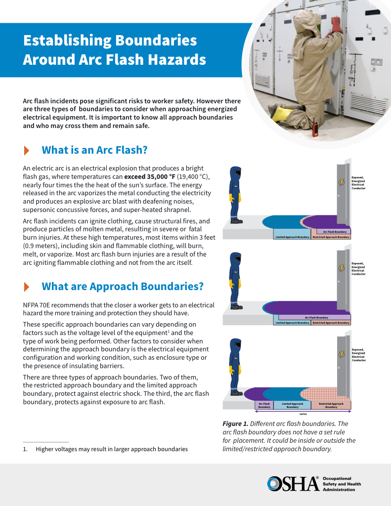
- Understand the difference between arc flash and electric shock boundaries
- Learn who may cross each boundary and under what conditions
- Apply voltage-based rules for safer approach distances
An arc flash boundary is the distance from an energized electrical source at which the incident energy equals 1.2 calories per square centimeter, the threshold for a second-degree burn specified in NFPA 70E Article 100.
This boundary defines where specialized arc-rated PPE and controlled work planning are required under NFPA 70E. It is not a theoretical safety buffer, but a calculated control used in hazard analysis, job planning, and energized work authorization.
Inside the arc flash boundary, the work stops being routine, even if the task looks routine. Entry into this zone changes who may approach the equipment, what protective equipment must be worn, and whether work can proceed while the equipment is energized. The boundary converts abstract electrical behavior into a physical decision line that governs access, protection, and accountability.
The boundary distance is established through engineering analysis that considers available fault current, protective device clearing time, working distance, and equipment configuration. Its purpose is to control exposure in real working environments, which is why boundary distances directly affect task authorization and PPE selection during formal analysis. For readers new to the topic, a broader explanation of arc flash hazards and terminology is available in the main arc flash overview.
This page explains what an arc flash boundary is, how it is established, and how it is applied in real working conditions. It does not function as a calculation table or a shortcut guide. For quick reference comparisons, see the arc flash boundary chart.
Why the Arc Flash Boundary Matters
The arc flash protection boundary exists because thermal injury from an arc fault occurs faster than human reaction. Once an arc initiates, the temperature rise and radiant heat exposure develop in milliseconds. Distance becomes the only remaining protective variable.
Sign Up for Electricity Forum’s Arc Flash Newsletter
Stay informed with our FREE Arc Flash Newsletter — get the latest news, breakthrough technologies, and expert insights, delivered straight to your inbox.
Arc flash injuries repeatedly follow the same pattern: workers were too close, insufficiently protected, or unaware of how far the hazard extended. These failures are not usually caused solely by negligence, but by reliance on assumed distances rather than calculated limits. Real-world injuries consistently demonstrate that proximity and protection determine outcome.
The boundary is grounded in exposure physics, not convention. Thermal energy radiates outward from an arc, and injury severity declines predictably with distance. Occupational Safety and Health Administration treats burns as a function of energy and proximity, not voltage alone. The arc flash boundary formalizes that relationship into a usable safety control.
This boundary forces deliberate decisions before a panel is opened, not after something goes wrong. It determines when arc-rated PPE is required, who is permitted to enter the area, and whether energized work can be justified. Organizations that treat the arc flash boundary as a working control rather than a label demonstrate a mature approach to electrical safety. Combined with training, hazard awareness, and system maintenance, it becomes one of the most effective tools for managing electrical risk.
Understanding how calculated arc flash boundaries translate into enforceable work practices begins with the obligations defined in electrical safety requirements, which connect hazard evaluation to procedural controls.
Request a Free Training Quotation
What the Arc Flash Boundary Represents in Practice
In practical terms, the arc flash boundary marks the transition between tolerable thermal exposure and serious burn hazard. Inside this boundary, arc-rated PPE is mandatory, access is limited to qualified personnel, and work must be formally planned and authorized. Outside it, the probability of thermal injury drops sharply, and routine activities may be performed without specialized protection.

The boundary is not fixed by voltage. Two systems operating at the same voltage can have dramatically different boundaries depending on fault current, clearing time, enclosure size, and conductor configuration. This variability is precisely why calculation, rather than assumption, is required.
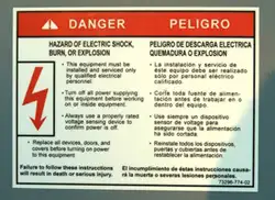
The meaning of an thermal hazard boundary is reinforced by the information presented on the arc flash warning label. That label converts engineering analysis into field-level decision support, allowing workers to judge proximity, PPE, and task risk before approaching energized equipment.
Why the Arc Flash Boundary Exists
Arc flash injuries rarely result from a single mistake. They occur when risk is underestimated, system behavior is misunderstood, or generalized distances are used instead of calculated limits. The NFPA 70E boundary distance exists to interrupt that chain of failure before work begins.
Arc flash boundaries are not arbitrary distances. They are derived from fault behavior identified through hazard analysis, which determines how far thermal energy can extend under worst-case conditions.
By establishing a clear minimum distance, the boundary supports several critical safety functions. It prevents unqualified personnel from entering hazardous zones, guides PPE selection, supports job planning and energized work permits, and provides a defensible basis for labeling, barricading, and training. Without a calculated boundary, organizations are left guessing, and guessing is what leads to severe burn injuries.
How Arc Flash Boundary Distance Is Determined
The arc flash boundary is established through engineering analysis, not rule-of-thumb distances or generic charts. It is calculated using recognized methods, most commonly those defined in IEEE 1584 and applied through NFPA 70E arc flash requirements and CSA Z462.
IEEE 1584 provides the mathematical model for calculating incident energy. NFPA 70E and CSA Z462 define how those calculated results are applied within safety programs, labeling, PPE selection, and work authorization. The documents serve different roles but work together.
Electricity Today T&D Magazine Subscribe for FREE

- Timely insights from industry experts
- Practical solutions T&D engineers
- Free access to every issue
The calculation identifies the distance at which incident energy decays to 1.2 cal/cm², the threshold for a second-degree burn. Several variables influence this distance, including system voltage, available fault current, protective device clearing time, working distance, and equipment configuration.
Because these variables interact, boundary distances can vary significantly even within the same facility. A motor control center protected by a fast-clearing breaker may have a much smaller boundary than similar equipment fed through slower upstream protection.
Calculations may be performed manually for educational purposes, but in operating facilities, analysis software is typically used to model complex systems accurately. Regardless of the method, the objective is the same: establish a boundary that reflects real operating conditions rather than idealized assumptions.
Incident Energy and Boundary Distance
Incident energy is the primary driver of arc flash boundary size. As incident energy increases, the boundary expands, sometimes dramatically. This is why boundaries cannot be generalized or reused across equipment without analysis.
At lower incident energy levels, boundaries remain close to the equipment. At moderate levels, such as 8 cal/cm², boundaries often extend to approximately 36 inches for common low-voltage systems. At higher energy levels, boundaries may extend several feet, requiring extensive controls, barricading, and heavier PPE.
Charts that relate incident energy to boundary distance illustrate trends, not guarantees. They are useful for reference, but boundary distances used for work authorization must always be based on calculated system data.
Understanding the 8 cal/cm² Arc Flash Boundary
An incident energy level of 8 cal/cm² is often discussed because it represents a moderate but serious burn hazard. The arc flash boundary for 8 cal/cm² is not the distance where a worker experiences 8 cal/cm². It is the distance where that energy decays to 1.2 cal/cm².

In many 480-volt systems, this boundary is often near 36 inches, but that value is not universal. Fault current, clearing time, enclosure size, and electrode configuration can all increase or reduce the distance. This is why site-specific calculation is essential.
Within this boundary, arc-rated clothing with an arc rating of at least 8 cal/cm² is typically required, along with additional protective equipment based on task exposure and arc flash PPE requirements. The boundary ensures that PPE selection and work authorization are based on realistic exposure rather than nominal ratings.
Relationship to Shock Protection Boundaries
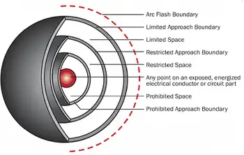
The arc flash boundary addresses thermal hazards, not electric shock. NFPA 70E also defines shock protection boundaries, including the limited approach boundary, which control proximity to energized conductors based on voltage.
These boundaries address different hazards but are applied together during energized work. A worker may be outside the shock boundary but inside the arc hazard boundary, or vice versa. Effective job planning considers both hazards simultaneously rather than treating them in isolation.
Teams sometimes confuse the arc flash boundary with approach boundaries for shock, but they control different injuries and can point to different stand-off distances for the same task
Marking and Communicating the Boundary
A calculated boundary only protects workers if it is clearly communicated. Common methods include labels that display boundary distances, floor markings near equipment, temporary barricades during energized tasks, and reinforcement through training and pre-job briefings.
Labeling practices and compliance expectations are addressed in NFPA 70E guidance. Clear visual and procedural communication reduces the likelihood of accidental exposure and supports consistent decision-making in the field.
Real-World Application
In real facilities, the arc flash boundary directly affects how tasks are performed. A panel with a calculated boundary of 36 inches may require barricading during energized troubleshooting. Higher-energy switchgear may require remote operation, extended clearances, or complete de-energization before work proceeds.
The boundary translates complex electrical analysis into enforceable behavioral controls. It defines where people may stand, what they must wear, and whether the task should proceed at all.
As one senior electrical safety manager summarized during a facility audit: “Boundaries turn calculations into behavior. Without them, analysis never leaves the report.”
Why Accurate Boundaries Matter
The arc flash boundary is not a theoretical exercise. It is a primary safety control that protects workers from catastrophic injury. When boundaries are accurately calculated, clearly marked, and consistently enforced, they significantly reduce the likelihood of severe burns and fatalities.
Organizations that integrate boundary calculations into daily work planning demonstrate a commitment to prevention rather than reaction. Combined with proper training, system maintenance, and hazard awareness, the arc flash boundary remains one of the most effective tools for managing electrical risk.
Related Articles

