Harmonic Distortion
Harmonic distortion is the deviation from the ideal electrical waveform caused by nonlinear loads. It impacts power quality, increases heat in equipment, and can lead to system inefficiencies. Monitoring and mitigation are essential in industrial electrical systems.
Harmonic Distortion and Its Impact on Workplace Safety
In the 1930s and 1940s, the primary sources were transformers, with the primary problem being inductive interference with open-wire telephone systems. Early arc lighting caused similar concern due to its harmonic content, just as today’s electronic power converters do.
Today, nonlinear devices like variable frequency drives (VFDs), arc furnaces, computer power supplies, and LED lighting introduce significant harmonic distortion into electrical systems. Nonlinear devices do not draw current in a linear relationship to voltage, which distorts the sinusoidal waveform and introduces harmonic currents. Harmonic distortion is one of the many issues covered in our comprehensive Power Quality resource channel, which explores causes, effects, and solutions.
Why It Matters
-
Harmonics degrade power quality
-
Increase energy losses and heat in conductors and transformers
-
Lead to premature failure of motors and sensitive electronics
-
Interfere with communication lines
In contrast, voltage sags and interruptions are nearly universal to every feeder and represent the most numerous and significant power quality deviations. The end-user sector suffers more from harmonic problems than the utility sector. Industrial users with adjustable speed drives, arc furnaces, induction furnaces, and similar equipment are significantly more susceptible to problems caused by harmonic distortion. To understand the relationship between harmonics and apparent energy flow, see our explanation of Apparent Power vs Real Power.
A good assumption for most utilities in the United States is that the sine wave voltage generated in central power stations is very good. In most areas, the voltage found on transmission systems typically has much less than 1% distortion. However, the distortion increases as the load approaches. At some loads, the current waveforms barely resemble a sine wave. Electronic power converters can chop the current into seemingly arbitrary waveforms. Managing nonlinear loads often requires Power Factor Correction to reduce harmonic effects and improve efficiency.
Industry Standards
-
IEEE 519: Sets recommended harmonic limits for both voltage and current.
-
IEC 61000-4-7: Defines methods of measuring harmonics and interharmonics.
Harmonic Distortion and Nonlinear Devices
Harmonic distortion is caused by nonlinear devices in the power system. A nonlinear device is one in which the current is not proportional to the applied voltage. Figure 1 illustrates this concept using the case of a sinusoidal voltage applied to a simple nonlinear resistor, where the voltage and current vary according to the curve shown. While the applied voltage is perfectly sinusoidal, the resulting current is distorted. Increasing the voltage by a few percent may cause the current to double and exhibit a different waveform. You can calculate your system’s power quality impact using our Apparent Power Calculator for precise performance metrics.
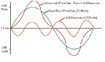
This is the source of most harmonic distortion in a power system. Figure 1 illustrates that any periodic, distorted waveform can be expressed as a sum of sinusoids. When a waveform is ideal from one cycle to the next, it can be represented as a sum of pure sine waves in which the frequency of each sinusoid is an integer multiple of the fundamental frequency of the distorted wave. This multiple is called a harmonic of the fundamental, hence the name of this subject matter. The sum of sinusoids is referred to as a Fourier series, named after the great mathematician who discovered the concept. Nonlinear loads like VFDs and arc furnaces can affect grounding; learn more in our guide to Electrical Grounding.
Fig. 1. Current distortion caused by nonlinear resistance
Voltage and Current Distortion
The term "harmonics" is often used by itself without further qualification. Generally, it could mean one of the following three:
-
The harmonic voltages are too great (the voltage is too distorted) for the control to properly determine firing angles.
-
The harmonic currents are too great for the capacity of some devices in the power supply system, such as transformers, and the machine must be operated at a lower than rated power.
-
The harmonic voltages are too great because the harmonic currents produced by the device are too great for the given system condition.
Clearly, there are separate causes and effects for voltages and currents, as well as some relationship between them. Thus, the term harmonics by itself is inadequate to describe a problem definitively. Nonlinear loads appear to be sources of harmonic current, injecting harmonic currents into the power system. For nearly all analyses, it is sufficient to treat these harmonic-producing loads simply as current sources. There are exceptions to this as described later.
Fig 2. Harmonic currents flowing through the system impedance result in harmonic voltages at the load.
Voltage distortion is the result of distorted currents passing through the linear, series impedance of the power delivery system, as illustrated in Fig. 2. Although assuming that the source bus is ultimately a pure sinusoid, there is a nonlinear load that draws a distorted current. The harmonic currents passing through the system's impedance cause a voltage drop for each harmonic. This results in voltage harmonics appearing at the load bus. The amount of voltage distortion depends on the impedance and the current. Assuming the load bus distortion stays within reasonable limits (e.g., less than 5%), the amount of harmonic current produced by the load is generally constant.
While the load current harmonics ultimately cause voltage distortion, it is worth noting that the load has no control over the voltage distortion. The same load put in two different locations on the power system will result in two different voltage distortion values. Recognition of this fact is the basis for the division of responsibilities for harmonic control that is found in standards such as IEEE Std 519-1992.
-
Control over the amount of harmonic current injected into the system occurs at the end-use application.
-
Assuming the harmonic current injection is within reasonable limits, the control over voltage distortion is exercised by the entity that controls the system impedance, typically the utility.
One must be careful when describing harmonic distortion phenomena, as there are distinct differences between the causes and effects of harmonic voltages and currents. The use of the term harmonics should be qualified accordingly. By popular convention in the power industry, the term is used by itself most of the time when referring to load apparatus, indicating that the speaker is referring to the harmonic currents. When referring to the utility system, the voltages are generally the subject. For systems affected by harmonic-induced overheating, understanding Capacitor Bank applications is essential for voltage support and harmonic filtering. For in-depth harmonic analysis, explore our guide to using a Power Quality Analyzer to identify waveform distortion and power anomalies.
Related Articles