Capacitance in Series
Capacitance in series reduces the overall capacitance by summing the reciprocals of the individual capacitors. This concept is essential in electronics, circuit analysis, and power systems, ensuring proper charge storage, voltage division, and reliable circuit performance.
Capacitance in Series: A Practical Guide
In a series circuit, connecting more than one capacitor in series affects the distribution of voltage and charge, directly impacting the system's total capacitance. Unlike parallel arrangements, a series setup reduces the overall capacitance and requires the use of a reciprocal formula to calculate the correct value.
This configuration functions as a voltage divider, with the total voltage split across each capacitor according to its capacitance. While this reduces the system’s ability to store charge, it also controls how voltage is allocated, which is useful in applications that require precise energy storage and voltage regulation.
For a clearer technical explanation, see our what is capacitance page, which breaks down how this key property affects circuit design.
When working with individual capacitors in electronic circuits, it is essential to understand their behaviour and the effects they have. For example, in a series arrangement, the positive plate of one capacitor is connected to the negative plate of the next capacitor. This unique connection affects the circuit's total equivalent capacitance (C_total), resulting in a total capacitance that is smaller than the smallest individual capacitance (C) present in the series. The total capacitance of capacitors in series is always less than the value of the smallest individual capacitor in the arrangement.
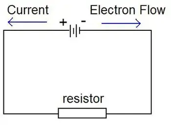
A series circuit is characterized by a linear sequence of components through which current flows in a single path. In such circuits, the total voltage is distributed across each component in proportion to its resistance. The overall resistance of a series circuit is equal to the sum of the individual resistances of the connected components. The unit of capacitance, the farad, measures a capacitor’s ability to store electric charge per unit voltage.
When they are connected in series, the total circuit capacitance is affected. This is because the positive plate of the capacitors is connected in series to the total C. Each capacitor stores the same charge in this arrangement, and the total voltage is divided across the capacitors in proportion to their C. This characteristic of series-connected capacitors plays a significant role in designing electronic circuits that require specific voltage and charge distribution properties. To fully grasp how capacitors behave in series, it’s important to understand what is a capacitor and how it stores and releases electrical energy.
Capacitors in Series: Formula, Voltage, and Charge Characteristics
| Feature | Capacitors in Series |
|---|---|
| Total Capacitance | Less than the smallest individual capacitor |
| Formula | 1/Ctotal = 1/C? + 1/C? + 1/C? + ... |
| Voltage Distribution | Voltage divides across capacitors based on capacitance values |
| Charge on Capacitors | Same charge on all capacitors |
| Use Case | Used when reduced overall capacitance is needed in a circuit |
| Energy Storage | Lower total energy storage than a single capacitor with same voltage |
Different types of capacitors, such as ceramic or electrolytic, behave differently in series configurations based on their construction and rated voltage.
Formula for Calculation
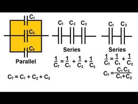
To accurately calculate the total C of capacitors connected in series, the following formula is employed:
C_total = 1 / (1/C1 + 1/C2 + 1/C3 + ... + 1/Cn)
This formula calculates the inverse of the total C. To find the actual total C, take the inverse of the sum of the inverse individual capacitances. This mathematical process enables the precise determination of the overall capacitance in a series configuration, which is crucial for designing or analyzing electronic circuits.
Impact of the Smallest Capacitor on Total Capacitance
When several are connected in series, the total C becomes smaller than the smallest individual C. This phenomenon occurs because the capacitor with a smaller capacitance (C) limits the total capacitance (C), acting as a bottleneck for current flow and restricting the total charge stored in the circuit. Understanding this limiting effect is critical when selecting capacitors for a series configuration, as the smallest capacitor will significantly impact the overall performance of the electronic circuit. Engineers must also consider electrical resistance, which affects how current and voltage interact with capacitors in mixed-component circuits.
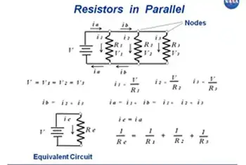
Comparing Capacitors in Parallel and Series Configurations
In contrast to capacitors in series, when capacitors are connected in parallel, the total C is the sum of the individual capacitances. This difference occurs because each capacitor is directly connected to the power source in a parallel circuit, allowing it to store its charge independently. Consequently, capacitors in parallel configurations offer higher overall capacitance, making them suitable for applications that require increased charge storage. Reviewing electrical resistance definition can help clarify how resistance and C work together in impedance-sensitive designs. You can explore how capacitance behaves in parallel versus in series when designing circuits that require larger energy storage.
Equivalent Capacitance and Voltage Drop in Series Capacitors
The equivalent C of capacitors connected in series can be determined by dividing the total charge stored in the circuit by the total voltage across the circuit. This is because the total charge stored in the circuit equals the sum of the charges on each capacitor. In contrast, the total voltage is calculated to determine the total capacitance for the number of capacitors connected.
The voltage drop in capacitors connected in series is divided among the capacitors in proportion to their C. This means that the voltage across each capacitor is proportional to its C. Understanding the voltage drop distribution in series capacitors is essential when designing circuits that rely on specific voltage levels across components.
Replacing Capacitors in Series with a Single Equivalent Capacitor and Combination Circuits
In some cases, a series of capacitors can be replaced with a single equivalent capacitor with the same C value as the series capacitors' equivalent capacitance. This replacement technique can simplify circuit design and analysis, consolidating multiple components into a single element with equivalent electrical properties.

In a combination circuit, capacitors are connected in both series and parallel configurations. These complex arrangements are commonly used in practical electronic applications because they offer greater flexibility and adaptability in achieving desired circuit properties. To calculate the total C of a combination circuit, first, compute the capacitance of each series combination, then add those capacitances to find the total C. This process may involve several steps, as the designer needs to consider the contributions of both series and parallel components to the overall C value.
Applications and Considerations of Capacitors in Series
Capacitors in series configurations are used in various electronic applications, such as power supply filtering, signal coupling and decoupling, and tuning and timing circuits. When designing these applications, engineers must consider the capacitors' voltage ratings, tolerances, temperature coefficients, and other parameters to ensure the circuit functions as desired.
One crucial consideration when working with capacitors in series is the voltage rating. The voltage rating of each capacitor must be sufficient to withstand the voltage applied across it. Since the total voltage is distributed among the capacitors in series, selecting capacitors with appropriate voltage ratings is essential to prevent component failure or degradation.
Another important consideration is the capacitors' tolerances, which indicate the possible variation in C values from their nominal specifications. Capacitors with tighter tolerances may be required for precise applications, as variations in C values can impact the overall performance of the electronic circuit.
Related Articles

_1497176406.webp)