Resistance in Series Explained
By William Conklin, Associate Editor
Resistance in series describes a circuit where resistors are connected end to end so the same current flows through each one. Total resistance equals the sum of values, shaping voltage drop, current flow, and circuit behaviour.
A series circuit uses a single current path, which makes its electrical behavior highly predictable. Because the current does not split, changes in resistance directly affect voltage distribution across the circuit. This makes series circuits especially useful for illustrating how resistance controls current and how voltage is shared among components, forming the foundation for analyzing more complex electrical networks. To understand how resistance behaves mathematically in circuits, review the fundamentals of electrical resistance and how it limits current flow.
Understanding How Resistance in Series Works
When resistors are connected in series, their individual resistances add directly. To find the total resistance of the circuit, each resistor value is added together using the formula:
Rtotal = R1 + R2 + R3 + …
This relationship shows why adding more resistors in series always increases total resistance. Each component adds resistance to the current, making it harder for the current to flow through the circuit.
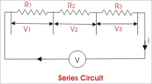
Ohm’s law applies cleanly to series circuits. The current remains constant throughout the circuit, while the voltage divides across each resistor in proportion to its resistance. A higher resistance results in a larger voltage drop, while a lower resistance produces a smaller drop. The sum of all voltage drops across the resistors always equals the source voltage. Series circuits follow predictable rules governed by Ohm’s law, which relates voltage, current, and resistance.
Because of this additive effect, the total resistance in a series circuit is always greater than the resistance of any single resistor in that circuit.
How to Calulate Total Resistance
To calculate total resistance in electrical systems, it is important to understand how resistors behave in series and in parallel. In a series connection, electric charges move through a single path, driven by the electromotive force of the source, and each resistor adds to the overall opposition to current flow. In contrast, a parallel circuit provides multiple paths for electric charges, allowing current to divide while the voltage remains the same across each branch. These differences explain why series and parallel circuits respond differently to the same supply conditions and why engineers must choose the correct arrangement for a given application.
In more complex designs, series and parallel combinations are often used to balance voltage, current, and power requirements. By mixing resistors in series and those connected in parallel, designers can fine-tune circuit behavior in ways that neither configuration could achieve alone. Understanding series and parallel combinations allows accurate prediction of current distribution, voltage drops, and power dissipation across a network. This is why mastering series and parallel circuits is essential for analyzing real-world electrical systems, from simple control circuits to larger power and distribution networks.
R in Series - Parallel
When resistors are placed in series, their ohmic values add arithmetically to determine the total resistance. This principle becomes especially useful when combined with parallel arrangements to form series-parallel networks. Calculating total opposition to current becomes clearer when comparing series connections with parallel resistances, where current divides rather than voltage.
In practical applications, as seen below, series-parallel networks are used to achieve resistance values and power ratings that are not available from a single component. By arranging equal-value resistors into series strings and then connecting those strings in parallel, designers can increase the network's overall power-handling capability while maintaining a specific equivalent resistance.
Three resistors in series.
In certain symmetrical arrangements, the equivalent resistance of a series-parallel network can equal the value of a single resistor. This occurs in configurations known as n-by-n matrices, where identical resistors are arranged as either n series branches in parallel or n parallel branches in series. Electrically, both arrangements produce the same result.
Power Handling in Series-Parallel Networks
An important advantage of series-parallel resistor networks is increased power-handling capability. Each resistor in the network dissipates power independently, and the total power the network can safely handle is the sum of the individual resistors' power ratings, provided the load is shared evenly. The concept of total circuit resistance is formally defined as equivalent resistance, which simplifies the analysis of complex resistor networks.
In a symmetrical network built from identical resistors, the voltage divides evenly across the series elements, and the current divides evenly among the parallel branches. Because of this balance, no single resistor is forced to dissipate more power than it is rated for. As long as each resistor operates within its voltage, current, and wattage limits, the entire network can handle a higher total load.
For example, a 3-by-3 matrix contains 9 identical resistors. If each resistor is rated for 2 W, the total power-handling capacity of the network is:


9 resistors × 2 W per resistor = 18 W
Each resistor still dissipates no more than 2 W, but together they allow the circuit to handle a much higher total power level.
The same principle applies to larger networks. A 10-by-10 matrix contains 100 identical resistors. If each resistor is rated for 0.5 W, the network can safely dissipate:
100 resistors × 0.5 W per resistor = 50 W
In both cases, the increased power rating comes from distributing the electrical load across many components, not from pushing any single resistor beyond its limits.
This approach only works reliably when all resistors have closely matched resistance values and power ratings. If one resistor differs, it may carry more current or drop more voltage than intended, leading to overheating and failure. Once one resistor fails, the electrical load shifts to the remaining components, increasing stress and raising the risk of cascading failures.
For this reason, good design practice includes a safety margin. If a resistor network is expected to dissipate 50 W, it should be designed to handle at least 55 W. Excessive overdesign is unnecessary. Still, an insufficient margin significantly increases the risk of premature failure. For a broader foundation that ties series circuits into larger systems, see this overview of electricity fundamentals.
Related Articles