10 Most Common Arc Flash Analysis Errors
By Frank Baker, Associate Editor
CSA Z462 Arc Flash Training – Electrical Safety Compliance Course
Our customized live online or in‑person group training can be delivered to your staff at your location.

- Live Online
- 6 hours Instructor-led
- Group Training Available
Download Our OSHA 4475 Fact Sheet – Being Aware of Arc Flash Hazards
- Identify root causes of arc flash incidents and contributing conditions
- Apply prevention strategies including LOTO, PPE, and testing protocols
- Understand OSHA requirements for training and equipment maintenance
The 10 Most Common Errors in Arc Flash Analysis include misapplication of NFPA 70E and IEEE 1584, PPE selection mistakes, incident energy miscalculation, poor protective device coordination, improper labelling, incorrect working distance, and outdated short-circuit data.
Explain the 10 Most Common Errors in Arc Flash Analysis
Many arc-flash studies fail due to recurring errors, such as misusing NFPA 70E or IEEE 1584, applying incorrect PPE levels, or relying on outdated equipment data. Misapplied IEEE 1584 models or parameters can distort incident energy results, while inaccurate arc-rated labelling and improper PPE selection expose workers to unnecessary risk. Poor device coordination is another frequent pitfall, as extended clearing times significantly increase the arc flash hazard and undermine the reliability of the overall analysis.
Top 10 Arc Flash Analysis Errors - Every month, we receive project files from a variety of customers seeking assistance or a file review. This top 10 list reflects some of the common errors when it comes to Arc Flash Analysis/Studies
Visit Our Arc Flash Study Course Page:
For a concise primer on planning and deliverables, our arc flash study overview can help frame the project scope.
#1 Starting Too Large
Generally, beginners in arc flash modelling and analysis tend to be in a hurry. Many try to draw the complete one-line diagram only to find that some important data was not entered on many of the elements, or worse, was not even collected by the data collection team. Attempting to start short-circuit analysis without entering all the required data only exacerbates the situation, as the first analysis attempt generates a long list of errors.
It is best to start with a very small representative one-line that includes a minimum set of system elements. This allows you to verify that the required data is sufficient to produce the expected results and generate the correct label contents. This approach also helps develop a solid understanding of the program's mechanics and an awareness of the variables that influence the calculations. For a step-by-step kickoff checklist, see how to perform an arc flash study to structure data collection and early validation.
Electricity Today T&D Magazine Subscribe for FREE

- Timely insights from industry experts
- Practical solutions T&D engineers
- Free access to every issue
#2 Improper System Modeling
The message “No Valid Device Found” is frequently displayed when a protective device that should limit arc time during a fault is missing. In these cases, try inserting a fuse in the location of the utility cutout switch. With this simple addition to the one line, virtually every bus in the system will reflect an incident energy if properly connected. This also emphasizes the common error that data for the protective devices in the system has not been properly completed. In EasyPower, this means the protective device's data dialogue box should include entries on at least three tabs, including the Phase Trip tab. To cross-check modelling choices against method assumptions, consult arc flash analysis for device data considerations.
#3 “No, 208V AC buses should not see 175 cal/cm2 (fed by 125kVA or less). “
When the project manager saw this label as part of a preliminary arc flash report from his consultant, he called to ask if this is something he should expect to see on a 208V bus. A quick check of the one-line showed the upstream transformer was rated at less than 125 kVA, so the answer is a definite, “No!”
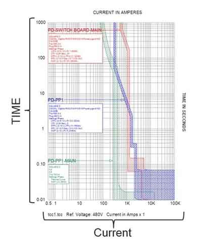
Creating a TCC plot for the MCCB upstream of the transformer quickly revealed that the adjustable instantaneous trip setting was misadjusted, as the calculated arcing current fell directly within the vertical band of the TCC plot. A small readjustment to the trip setting repositioned the instantaneous set point and lowered the incident energy to a respectable 0.4 cal/cm2. For context on what drives these values, review the fundamentals of incident energy analysis and how settings affect calculated exposures.


#4 “Not all buses are created equal.”
The IEEE 399 (Brown Book) specifies that a short-circuit study should determine the worst-case fault current and compare it with the withstand ratings of each system element. As the one-line diagram is constructed, the capacity rating and withstand rating for each bus should be included as required data. These ratings may vary from panel to MCC to switchgear. In addition, the type of bus determines the air gap dimension used in the arc-flash model, as specified by the NEMA designation and set up in the device library. Consequently, accurate assignment of the type of each bus improves the overall results of the study. A quick refresher on equations and parameters is available in understanding arc flash calculations to support correct bus type inputs.
#5 Infinite Utility Data is Not the Conservative Approach
Aside from the system transformer, the utility data is one of the more important sets of parameters required to complete the one-line model. The default utility in EasyPower includes figures that represent an infinite source. While this permits calculations to be completed, the results may reflect device trips that are faster than they actually are. Every effort should be made to retrieve this data from the local utility company. When all else fails, some reference material can help estimate a realistic set of parameters if data from a local source is unavailable. When utility data is incomplete, follow the decision steps in how do I complete an arc flash hazard analysis to set realistic source parameters.
#6 Incorrect Working Distance
A high percentage of arc flash studies seem to stay with the default working distance for arc flash calculations. When conducting a study for clients, consulting firms may interact more frequently with factory management, but most electrical work is performed by maintenance staff or contract electricians. The people with intimate knowledge of the procedures and details of the manufacturers’ recommended maintenance should be consulted during data collection. Often, including the local hands-on team in the conversation helps ensure a better understanding of the hazards involved and leads to shared ownership of the safety standards developed. For procedural alignment with field practices, walk through 7 steps to arc flash analysis to confirm working distances and task definitions.
Sign Up for Electricity Forum’s Arc Flash Newsletter
Stay informed with our FREE Arc Flash Newsletter — get the latest news, breakthrough technologies, and expert insights, delivered straight to your inbox.
#7 Misapplication of the 2-Second Rule
There are 13 words that often seem to be overlooked when a study has set the maximum time for calculating arcing time for the whole plant to 2 seconds. Embedded in the last paragraph of NFPA 70E, D.4.3 you will find, “Sound engineering judgment should be used in applying the 2-second maximum clearing time…” If a system can release enough explosive energy to physically eject me from the vicinity, I most certainly want to ensure the PPE will protect me for the duration of my flight. I strongly resist the temptation to limit energy calculations for any system 480 volts or higher based on how easy it is to move back from the panel.
#8 “Our system has not changed, just recalculate the study.”
“Don’t bother collecting data; nothing has changed.” Does that mean no fuses were replaced? No relays or breakers were tweaked during an off shift to keep equipment running? Even if there were no substantial system changes, are you sure the utility substation did not change or that no other facilities were built in the area? The 5-year update is not an invitation for a rubber stamp. It is a time to review both the system and safety procedures. Are we interested in improving the worker safety in our plant, or do we just want to get another report set up on the shelf?
#9 Labels still have “Hazardous Risk Category” (HRC)
With the release of NFPA 70E-2015, we can no longer refer to HRC or place the HRC # on arc-flash hazard labels when the incident energy and working distance have been calculated for the bus. So, the question follows, “If my labels still have HRC and I completed the study in 2014, does that mean my study is non-compliant?”

Inasmuch as a label by itself does not mean the study was accurate, just because the label is non-compliant does not mean the study is non-compliant (as long as no system changes have occurred since the study was completed). It does mean the labels need to be changed.
“But I cannot change the label right away. What should I do?”
Simple. TRAIN your personnel to understand the changes in NFPA 70 and why the standard has changed. Explain how the changes affect your operation; that new labels will be changed out as time permits; and most of all, ensure all qualified workers can identify PPE requirements in terms of cal/cm2 and how to confirm the PPE they select meets the PPE requirements in terms of cal/cm2.
#10 Main Breaker ‘Excluded’ in Panel
If there is not a flash barrier between the incoming conductors to the main breaker in a panel and the main bus of that panel, then the main breaker may not be used to calculate incident energy for the main bus. The explosion during an arc flash event is caused by the rapid expansion in volume of the material (copper, aluminum, etc.), which is consumed from the heat generated by the plasma ball of the arcing event. If an arc is initiated between the bare conductors of the incoming cables to the main breaker of a panel and the resulting plasma ball extends so far that the main bus bars are involved, the result may mean the arc breaches the main breaker, rendering it useless to quench the arc. Consequently, the properties of the main trip device may not be used, and the next upstream tripping device must be used to calculate the panel's incident energy. This is another example of information that must be determined during data collection. The solution should not just be limited to procuring PPE with a higher calorie rating. The potential to relocate the protective device (fuse or breaker) outside the panel for improved isolation merits consideration.
Source: Easypower

