Single Phase Transformer Connections Explained
By William Conklin, Associate Editor
Substation Maintenance Training
Our customized live online or in‑person group training can be delivered to your staff at your location.
- Live Online
- 12 hours Instructor-led
- Group Training Available
Download Our OSHA 3875 Fact Sheet – Electrical PPE for Power Industry Workers
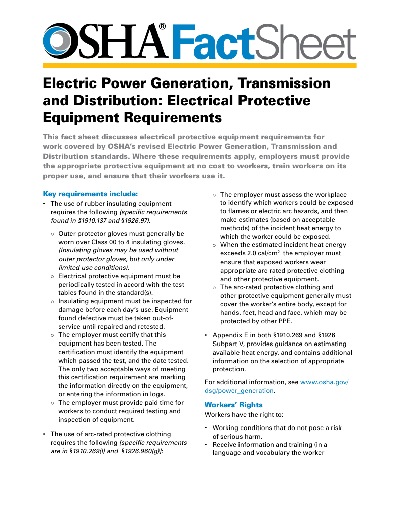
- Follow rules for rubber gloves, arc-rated PPE, and inspection procedures
- Learn employer obligations for testing, certification, and training
- Protect workers from arc flash and electrical shock injuries
Single phase transformer connections support safe voltage changes in AC systems, using series or parallel wiring, proper polarity, and load matching to maintain efficient power distribution.
Single phase transformer connections support efficient voltage transformation across residential, commercial, and industrial systems. What makes them practical is their ease of adaptation to different loads and service conditions, with careful attention to polarity, winding arrangement, and the intended operating voltage.
Electrical Transformer Maintenance Training
Substation Maintenance Training
Request a Free Training Quotation
Understanding Single-Phase Transformer Connections: Principles and Applications
Single-phase transformers can be wired in series or parallel, depending on the available voltage and the load to be served. In most distribution settings, the secondary windings are designed to be field-connected in either arrangement. Electricians choose the configuration that provides the correct output while keeping losses low and transformer loading within safe limits. Metering and protection devices, such as current transformers, often accompany these installations to scale down current for instruments and relays.
Although transformers operate strictly with alternating current, they do rely on consistent polarity markings. Polarity refers to the instantaneous relationship between the primary and secondary voltages. It does not behave like the positive and negative terminals on a DC source, yet it still matters when transformers are combined or paralleled. A control transformer, for example, depends on correct polarity to supply stable low-voltage control circuits in larger systems.
Single-phase transformer leads exit the case through insulated bushings, and the terminals follow a long-standing convention: the H terminals are on the high-voltage side, and the X terminals are on the low-voltage side. Either side may function as primary or secondary, depending on the application. By agreement, H1 and X1 share the same instantaneous polarity. This standard enables parallel transformers, temporary bank assembly, and integration of dry type transformers in facilities where noise reduction and fire safety are important.
FREE EF Electrical Training Catalog
Download our FREE Electrical Training Catalog and explore a full range of expert-led electrical training courses.

- Live online and in-person courses available
- Real-time instruction with Q&A from industry experts
- Flexible scheduling for your convenience
Fig. 1. Additive and subtractive transformer terminal markings
Manufacturers mount terminals in ways that produce either additive or subtractive polarity. Additive polarity places H1 diagonally across from X1, while subtractive polarity places them adjacent. Most larger distribution transformers follow subtractive polarity. As a general rule, units above 200 kVA or rated above 9,000 volts use subtractive polarity, while smaller, lower-voltage units are more often additive.
When markings are missing or unclear, technicians can run a quick polarity test. After identifying H1 and H2 by orientation, a jumper is placed between H1 and the adjacent low-voltage terminal. A voltmeter measures the difference between H2 and the remaining low-voltage lead as low voltage is applied to the primary. If the reading exceeds the applied voltage, the unit is additive and X1 is the right-hand terminal. If the reading is lower, the unit is subtractive, and X1 is on the left. This simple test shows how the induced secondary voltage either adds to or subtracts from the applied primary voltage. An isolation transformer, for instance, is often used to reduce noise or provide galvanic separation, and can be tested in the same way.
If the transformer leads are unmarked, a polarity test can be performed to identify and mark them. By convention, the top-left terminal when the transformer is viewed from its low-voltage side is always labelled H1. In addition to load balancing, specialized devices such as instrument transformers improve system monitoring and fault protection.
Fig. 2. Dual voltage transformer with its secondary windings connected in parallel.
Every transformer includes a wiring diagram, usually printed on the nameplate or inside the terminal compartment. Before two units are connected, three conditions must be met: their voltage ratings must match, their impedance percentages must be equal, and their polarities must align. Series connections are uncommon, but when transformers are placed in series, each winding must handle the full load current. Parallel connections, where current capacity increases, require the same attention to polarity and impedance to ensure the load is properly divided.
Fig. 3. Two single phase transformers connected in parallel.
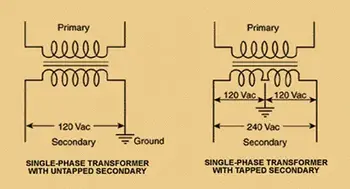
In some installations, transformers are placed in series to increase available voltage, while parallel windings allow for higher current at the same voltage. For example, when a 480-volt source must supply two 120-volt loads, two 240-volt primary windings can be wired in series so each drops half the source voltage. The secondaries then provide the required 120 volts to their respective loads.
Whether configuring a simple single-phase setup or integrating units into a three-phase bank, proper connections ensure stable operation, reduced losses, and safe performance in both utility and industrial environments.
Whether boosting voltage with a step-down transformer or configuring complex delta vs wye arrangements, proper connections ensure safe and efficient power distribution.
Related Articles
