Potential Transformer Explained
By Howard Williams, Associate Editor
Substation Maintenance Training
Our customized live online or in‑person group training can be delivered to your staff at your location.
- Live Online
- 12 hours Instructor-led
- Group Training Available
Download Our OSHA 4474 Fact Sheet – Establishing Boundaries Around Arc Flash Hazards
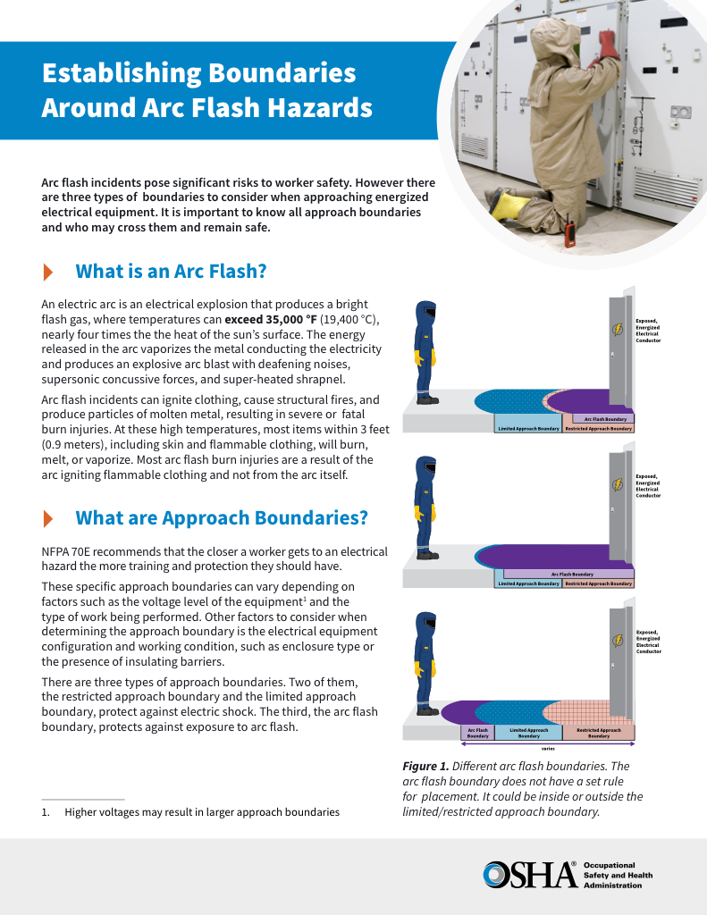
- Understand the difference between arc flash and electric shock boundaries
- Learn who may cross each boundary and under what conditions
- Apply voltage-based rules for safer approach distances
A potential transformer (PT) is an instrument transformer that converts high system voltage into a precise, lower secondary voltage so that protection systems, meters, and control equipment can see what the power system is actually doing. Without that translation, operators are not observing voltage; they are guessing. PTs exist to make high-voltage behavior measurable, actionable, and safe under both normal and fault conditions.
When voltage is measured incorrectly, protection systems misjudge fault conditions, meters misreport system performance, and operators lose reliable visibility into network behavior. Small PT errors can propagate into incorrect relay coordination, delayed breaker operation, and flawed power quality analysis. These failures rarely announce themselves directly, but they steadily weaken system reliability and safety margins.
Selecting and applying a potential transformer is therefore a protection and measurement decision, not a component convenience. Accuracy class, burden, insulation rating, and connection method determine whether downstream instruments reflect real system conditions or a distorted approximation. Engineers, technicians, and operators rely on PT performance to validate system health, confirm compliance, and make switching, protection, and maintenance decisions with confidence.
Potential Transformer Explained for Electrical Professionals
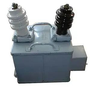
A potential transformer is an instrument transformer designed to step down a high primary voltage to a stable, proportional secondary voltage that standard measuring and protection devices can safely use. It allows voltage to be observed, recorded, and acted upon without exposing equipment or personnel to primary system levels.
Unlike power transformers, PTs are optimized for accuracy rather than energy transfer. They maintain a fixed ratio between the primary and secondary voltages so that phase angle, magnitude, and waveform integrity are preserved. This is what allows voltmeters, wattmeters, energy meters, and protective relays to correctly interpret system behavior.
Electricity Today T&D Magazine Subscribe for FREE

- Timely insights from industry experts
- Practical solutions T&D engineers
- Free access to every issue
Potential transformers are connected in parallel with the circuit being measured, so they reflect the true system voltage at that point in the network. Their accuracy class and burden rating determine how closely the secondary voltage matches the actual primary condition under load. In high-voltage applications where insulation and stability requirements increase, related transformer designs, such as capacitor voltage transformers, are often evaluated as alternative measurement solutions.
To compare potential transformers with similar components, explore our detailed guide on capacitor voltage transformers, commonly used in high-voltage applications.
Electrical Transformer Maintenance Training
Substation Maintenance Training
Request a Free Training Quotation
Construction
The construction of a potential transformer is governed by one priority: preserving voltage accuracy while isolating measuring systems from primary exposure. Precisely wound primary and secondary coils are arranged to maintain a fixed ratio relationship through electromagnetic induction. This proportional relationship allows secondary instruments to reflect true system voltage rather than a calculated approximation. Different PT constructions, including electromagnetic and capacitor-based designs, exist because insulation demands, voltage levels, and system stability requirements vary across applications. Selecting the wrong construction type does not usually cause immediate failure, but it gradually erodes measurement credibility and protection confidence. Since PTs are a subtype of instrument transformers, it is useful to understand how current transformers perform a similar isolation role for high-current measurement.
The working principle of a potential transformer reinforces its role as a measurement device rather than a power device. Through electromagnetic induction, PTs reproduce the primary voltage at a lower level while preserving ratio and phase integrity. When this relationship is distorted, protection logic, synchronization, and system analysis lose their reference point. Accurate voltage reproduction is therefore not a convenience, but a requirement for reliable power system operation.


Accuracy & Burden
PTs are rated by VA burden (e.g., 12.5?VA W-load, 25?VA X-load) and accuracy classes (0.3, 0.6X) per IEEE C57.13. These specifications define performance under load.
Despite their reliability, they are not immune to challenges. Errors, such as ratio errors and phase angle errors, can affect measurement accuracy. Ratio errors occur when the voltage ratio deviates from its intended value, while phase-angle errors disrupt the phase alignment between the primary and secondary voltages. Addressing these inaccuracies requires meticulous design and regular maintenance to ensure consistent performance. Understanding these errors is critical, as they can have a cascading impact on the system's overall functionality.
In protection and metering schemes, PT output is fundamental to how a protective relay interprets system conditions within coordinated power system protection designs.
Types of Potential Transformers
Potential transformers are not interchangeable components. Each design exists to solve a specific measurement and insulation problem created by voltage level, system configuration, and protection requirements. Understanding these differences is essential because the wrong PT type can compromise accuracy, stability, or long-term reliability even when the ratio appears correct on paper. For a broader context on transformer construction categories, dry-type transformer types and designs illustrate how insulation and cooling methods influence performance.
Electromagnetic Potential Transformer (EMPT):
This is the most commonly used type in medium-voltage applications. It consists of primary and secondary windings on a magnetic core and operates on the principle of electromagnetic induction. EMPTs are ideal for voltages up to 69?kV and are widely used in substations and industrial settings.
Capacitor Voltage Transformer (CVT or CCVT):
Used primarily in high-voltage applications (typically 69 kV to 800 kV), CCVTs step down high voltages using a capacitive voltage divider instead of magnetic windings alone. They are more cost-effective and compact at very high voltages and also provide relay and control system signal outputs. CCVTs are common in transmission networks.
Test Your Knowledge About Electrical Transformers!
Think you know Electrical Transformers? Take our quick, interactive quiz and test your knowledge in minutes.
- Instantly see your results and score
- Identify strengths and areas for improvement
- Challenge yourself on real-world electrical topics
Optical Voltage Transformer (OVT):
A newer, digital alternative, OVTs use fibre optics and electro-optic sensors to measure voltage. They offer advantages such as high accuracy, wide bandwidth, and electrical isolation. These are suitable for very high-voltage systems (up to 800 kV) and are increasingly used in smart grid and digital substation applications.
Typical Voltage Ranges:
-
Low to Medium Voltage: Electromagnetic PTs (up to ~69?kV)
-
High Voltage: CCVTs (from ~69?kV up to 800?kV)
-
Extra-High Voltage & Digital Applications: Optical PTs (up to 800?kV and beyond)
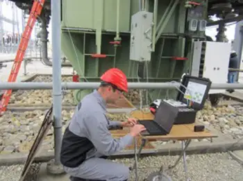
Each type plays a crucial role in ensuring accurate voltage measurement, protecting equipment, and monitoring the system across various voltage levels and power grid configurations. Discover how transformer testing is used to ensure accuracy and performance in both voltage and current transformers.
In practical applications, PTs are indispensable. They enable the precise operation of measuring instruments by accurately representing the high-voltage circuit. PTs are also used to protect electrical equipment by isolating measuring devices from the primary voltage, thereby enhancing safety and security. Additionally, they facilitate synchronization between generators and feeders, ensuring seamless operation in substations and throughout the broader power grid. PTs are a cornerstone of efficient power system management by delivering a reliable output voltage.
A potential transformer differs significantly from a regular one. While both devices operate on similar principles, their purposes diverge. Regular types primarily focus on power transfer between circuits, while PTs are dedicated to voltage measurement and monitoring. Furthermore, PTs are designed with higher accuracy to ensure the reliability of measuring instruments, making them vital components in settings where precision is paramount. See how PTs compare to step-down transformers, which also reduce voltage but serve different purposes in power distribution.
The distinction between current transformers (CTs) and PTs further highlights their specialized roles. CTs measure current, scaling down high current levels for safe monitoring, whereas PTs focus on reducing high voltage to a lower, measurable level. Both devices complement each other in electrical systems, collectively ensuring comprehensive monitoring and control.
In substations, the potential transformer serves a crucial function. They provide real-time voltage data for system operation, protection, and decision-making. By delivering accurate secondary voltage to control systems, PTs enhance substations' reliability and ensure optimal performance across the power network.
In modern substations, potential transformers provide voltage reference functions that integrate directly into substation protection systems, alongside equipment such as capacitor voltage transformers.
A potential transformer is a fundamental component of modern electrical infrastructure. Its ability to step down high voltages, provide accurate measurements, and protect systems from harm underscores its importance. It remains an indispensable tool for managing complex electrical systems, whether in substations, industrial plants, or power grids.
If you're looking for a foundational overview of all transformer functions and types, visit our comprehensive page on electrical transformers.
Related Articles

