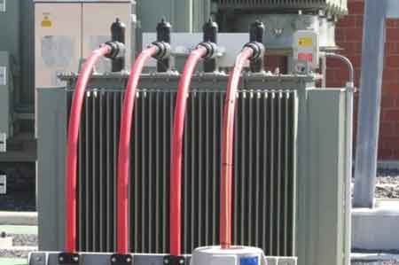
Earthing Transformer - Safety and Stability
By William Conklin, Associate Editor
Substation Relay Protection Training
Our customized live online or in‑person group training can be delivered to your staff at your location.
- Live Online
- 12 hours Instructor-led
- Group Training Available
Download Our OSHA 4474 Fact Sheet – Establishing Boundaries Around Arc Flash Hazards
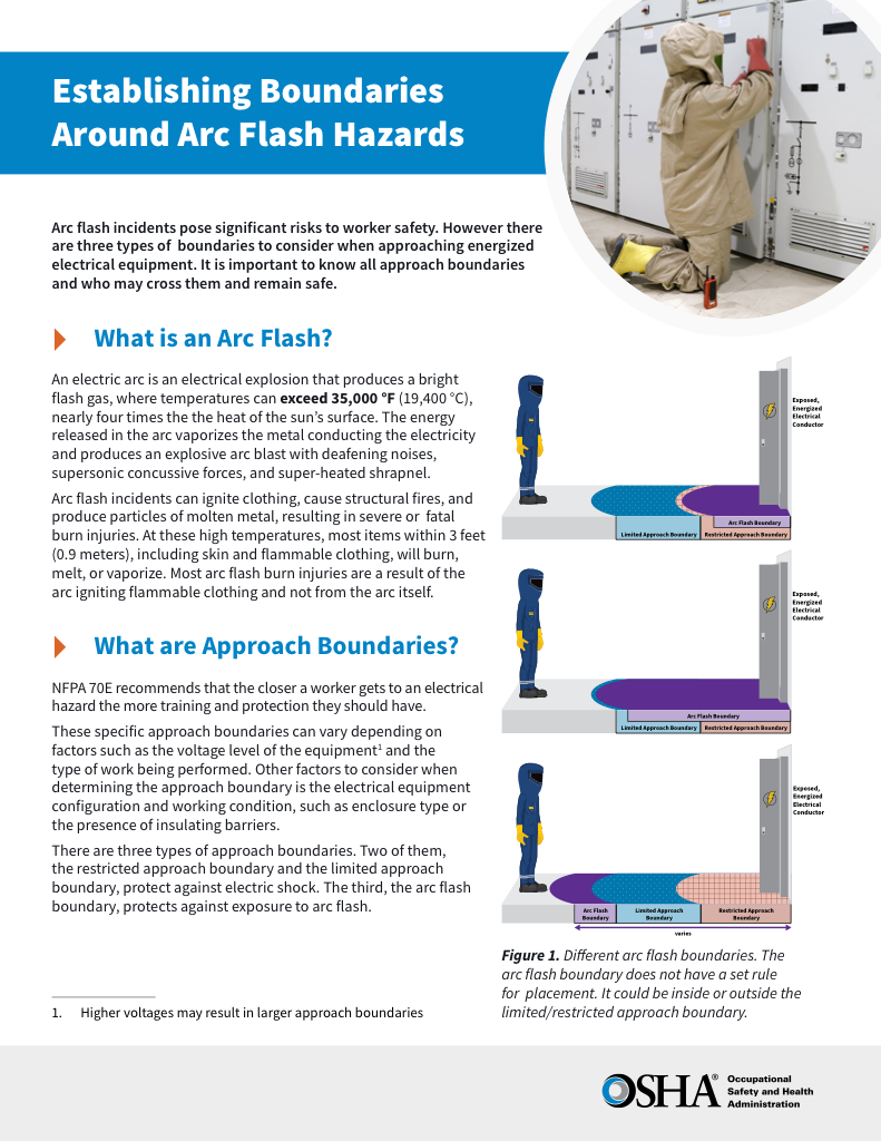
- Understand the difference between arc flash and electric shock boundaries
- Learn who may cross each boundary and under what conditions
- Apply voltage-based rules for safer approach distances
An earthing transformer provides a controlled neutral reference in ungrounded systems to shape ground-fault current, enable predictable protective relay operation, maintain phase-to-ground voltage stability, and reduce equipment risk in industrial and utility power networks.
Earthing Transformer: Neutral Reference and Fault Architecture
Earthing transformers create a deliberate neutral reference in ungrounded three-phase power systems, ensuring that ground faults result in controlled, measurable fault currents and that protective devices behave predictably rather than by chance. Without this engineered ground reference, phase-to-ground voltages can rise beyond safe limits, relays lack reliable fault directionality, and equipment exposure increases.
From a compliance and safety standpoint, earthing transformers are a structural element of electrical grounding design rather than an optional accessory.
In practice, specifying an earthing transformer is not about delivering load power; it is a design decision that defines how the system responds under ground-fault stress, shapes protective coordination, and anchors voltage stability across industrial and utility networks. This engineering context positions the device within a fault-control architecture rather than as a basic transformer.
When Earthing Transformers Are Required
Three-phase systems with delta configurations or other ungrounded topologies lack an inherent neutral to bond to earth. In these networks, a single line-to-ground fault produces ambiguous fault currents and undefined phase-to-ground potentials unless an engineered reference is provided. The purpose of an earthing transformer is to provide a reference so that protective relays detect faults reliably and clearing times meet coordination requirements.
The need for an earthing transformer is closely tied to system topology, particularly when evaluating delta vs wye grounding behavior and neutral availability.
Where a neutral already exists and is grounded through a utility transformer, designers evaluate how that ground reference impacts fault current levels, grounding impedance economics, and arc-flash risk before deciding if an additional device belongs in the system.
FREE EF Electrical Training Catalog
Download our FREE Electrical Training Catalog and explore a full range of expert-led electrical training courses.

- Live online and in-person courses available
- Real-time instruction with Q&A from industry experts
- Flexible scheduling for your convenience
How Earthing Transformers Create a Neutral
Earthing transformers introduce an artificial neutral point that can be tied to earth. The most prevalent configuration uses a zigzag winding to create a low-impedance neutral that supports zero-sequence current flow during ground faults. This design choice is technical, not stylistic — it directly influences how fault currents are shaped and how voltage stability is maintained under unbalanced conditions.
Their role must always be evaluated within the context of the overall grounding system, where voltage reference, fault return paths, and protective coordination are defined.
Understanding these winding choices and their impact on system behavior is part of specifying the device in protection and grounding design.
Fault Current Shaping and Protective Coordination
Once a neutral exists, the critical design decision becomes how much ground-fault current is permitted. Designers must balance:
• Protective device sensitivity and selectivity,
• Equipment interrupting ratings and thermal stress exposure,
• Phase-to-ground voltage limits during faults,
• Arc-flash boundary implications for personnel safety.
Ground-fault response must remain compatible with upstream transformer overcurrent protection limits so that protective devices operate within their intended duty.
An earthing transformer’s impedance becomes a design variable in protective coordination rather than a passive given.
When Not to Use an Earthing Transformer
In grounded wye systems where a dependable neutral reference is already available from a source transformer, direct grounding decisions shift to how that neutral is bonded and what impedance is acceptable for protective coordination. In such cases, specifying an earthing transformer is typically unnecessary or even detrimental to defined ground-fault behavior.
Proper performance depends on how the earthing transformer integrates with established grounding and bonding practices that govern fault current continuity and personnel safety.


In such cases, specifying an earthing transformer is typically unnecessary or even detrimental to defined ground-fault behavior.
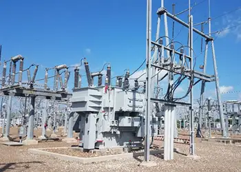
Application Context in Substations and Distribution
In real installations, earthing transformers are often present at substations and distribution points, where neutral availability and fault control influence feeder protection, relay settings, and continuity objectives.
In substation environments, their function directly influences protection behavior within electrical substation transformer installations.
Earthing transformers belong to the broader class of grounding transformers, which exist to control system fault behavior rather than to serve load demand.
Their presence has implications for system architecture that extend into grounding strategy, protective relay coordination, and safety compliance.
Design Impacts Engineers Must Consider
The choice to install an earthing transformer affects:
• Protective relay pickup and coordination margins,
• Phase-to-ground voltage stability during a ground fault,
• Equipment insulation and thermal exposure,
• Arc-flash risk profiles, and
• Maintenance planning tied to compliance boundaries.
An earthing transformer is therefore not a convenience; it is a structural decision in fault architecture, shaping how a network behaves during abnormal conditions and anchoring the performance of the protective system.
Related Articles
• Delta vs Wye Transformer Connections
• Transformer Overcurrent Protection
• Electrical Substation Transformer
