Grounding Transformers
By William Conklin, Associate Editor
Transformer Maintenance Training - Testing and Diagnostics
Our customized live online or in‑person group training can be delivered to your staff at your location.
- Live Online
- 12 hours Instructor-led
- Group Training Available
Download Our OSHA 3875 Fact Sheet – Electrical PPE for Power Industry Workers
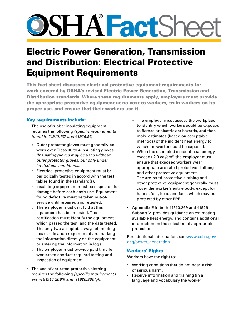
- Follow rules for rubber gloves, arc-rated PPE, and inspection procedures
- Learn employer obligations for testing, certification, and training
- Protect workers from arc flash and electrical shock injuries
Grounding transformers are commonly implemented as zig-zag or wye-delta configurations, depending on grounding method, system voltage, and protection coordination requirements.
Grounding transformers provide a controlled neutral reference for ungrounded or delta-connected power systems. By creating a stable earth connection, they improve fault detection, voltage stability, harmonic control, and overall system reliability in utility, industrial, and renewable energy networks.
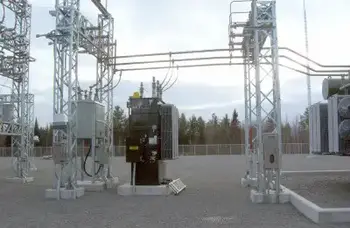
They are most commonly installed in substations, wind farms, distributed generation sites, and industrial plants where a grounded neutral is required but not naturally available from the system configuration. In utility distribution systems, they are commonly installed alongside electrical substation transformers to provide a stable neutral reference and support coordinated fault protection.
Electrical Transformer Maintenance Training
Substation Maintenance Training
Request a Free Training Quotation
Grounding Transformers in Power Systems
A grounding transformer is not installed to supply load power. Its role is protection and stability. It creates a neutral point, establishes a defined path for ground-fault current, and allows protective devices to operate correctly. Without this reference, ground faults can remain undetected, voltages can drift unpredictably, and insulation stress can increase across equipment.
In three-phase systems, grounding transformers are often paired with delta or ungrounded wye configurations to provide a practical solution while preserving system flexibility. Because grounding performance depends on transformer construction, engineers often evaluate the construction of a transformer when selecting grounding (earthing) configurations and zero-sequence impedance values.
Transformer grounding directly influences overall electrical earthing performance by controlling fault current paths, stabilizing phase voltages, and supporting reliable protection coordination.
Why Transformers Are Grounded
Grounding a transformer serves three essential functions.
Safety: A defined earth path prevents dangerous touch voltages and reduces the risk of electric shock and fire during faults.
Sign Up for Electricity Forum’s Utility Transformers Newsletter
Stay informed with our FREE Utility Transformers Newsletter — get the latest news, breakthrough technologies, and expert insights, delivered straight to your inbox.
System stability: Grounding limits overvoltage conditions and stabilizes phase-to-ground voltages during both normal and abnormal operation.
Fault protection: Grounding allows protective relays and breakers to detect ground faults quickly and isolate affected equipment before damage spreads.
Without proper earthing, ground faults may circulate unnoticed, creating long-term insulation stress and serious safety hazards. Proper earthing practices are closely tied to broader electrical grounding principles that define how fault currents return safely to earth.
Grounding Transformer Configurations
A zig-zag grounding transformer is commonly used to create a neutral point on ungrounded systems while supporting effective protection coordination during ground faults. In applications that require voltage transformation or system isolation, a wye-delta configuration is often preferred.
The selected method depends on system voltage, fault current levels, and relay coordination requirements. By matching the grounding transformer design to system voltage and protection philosophy, engineers ensure reliable fault performance and long-term system stability.
Methods of Transformer Grounding
Several grounding methods are used depending on system size, fault levels, and protection philosophy.
Solid: The neutral is directly connected to earth, producing high fault currents and fast fault clearing.
Resistance: A resistor limits fault current while maintaining a detectable fault level, reducing mechanical and thermal stress.
Reactance: A reactor limits fault current in systems with very high short-circuit capacity.
Ungrounded wye: No intentional ground connection. This allows continued operation during a single line-to-ground fault but requires careful monitoring.
Zig-zag grounding transformers: Provide grounding for delta or ungrounded systems while offering harmonic suppression and neutral stability.
For compliance and consistency, grounding transformer installations should align with recognized grounding and bonding practices used throughout power quality and protection systems.
Design and Sizing Considerations
Grounding transformers are selected based on their ability to carry ground-fault current for a defined duration while maintaining acceptable temperature rise and mechanical integrity.
Key design factors include zero-sequence impedance, system voltage class, and short-time current rating. In medium-voltage networks, grounding transformers are frequently paired with medium voltage transformers to control ground-fault current while maintaining insulation reliability.
| Parameter | Typical Range | Engineering Purpose | System Impact |
|---|---|---|---|
| Zero-sequence impedance | 1–10% | Controls ground fault current magnitude | Lower impedance enables faster relay operation |
| Short-time current rating | 200–2000 A for 1–10 seconds | Defines thermal and mechanical duty | Must withstand fault until protection clears |
| System voltage | 2.4 kV to 34.5 kV common | Matches insulation requirements | Determines insulation coordination |
| Continuous kVA rating | 50–2000 kVA typical | Based on system scale | Supports long-term operational stability |
The transformer must allow sufficient fault current for relay coordination while avoiding excessive equipment stress. This balance is central to grounding transformer engineering.
Harmonics and Power Quality
Zig-zag grounding transformers provide an effective path for triplen harmonics, including third, ninth, and fifteenth harmonics. By absorbing these components, they reduce voltage distortion and neutral instability in systems with nonlinear loads. In facilities with nonlinear loads, these transformers support harmonic control strategies discussed in power quality and harmonics analysis.
This function is especially important in facilities with variable-frequency drives, inverter-based renewable generation, and electronic power supplies.
Fault Behavior and Protection
When a ground fault occurs, a properly grounded system allows protective relays to detect abnormal zero-sequence current and isolate the faulted section rapidly. This limits thermal stress, prevents cascading outages, and protects connected equipment.
Without earthing, faults may shift voltages, overstress insulation, and remain undetected until more severe failures occur.
Standards and Codes
Grounding transformer design and application follow recognized international standards.
-
NEC provides rules for North American installations.
-
IEEE standards offer technical earthing and design guidance.
-
IEC standards define international earthing requirements.
Compliance ensures consistent safety performance and predictable protection behavior across different systems.
Consequences of Improper Grounding
Poor grounding design or maintenance can create serious operational problems.
-
Ground loops introduce interference and malfunction.
-
High impedance paths prevent fault detection
-
Unclear earthing points compromise maintenance safety.
-
Uncontrolled fault currents damage insulation and equipment.
Modern high-voltage and medium-voltage transformers depend on earthing to manage electrical stress and protect insulation systems.
FREE EF Electrical Training Catalog
Download our FREE Electrical Training Catalog and explore a full range of expert-led electrical training courses.

- Live online and in-person courses available
- Real-time instruction with Q&A from industry experts
- Flexible scheduling for your convenience
Best Practice Guidelines
Effective earthing requires:
-
Identifying the transformer neutral point.
-
Using conductors sized for the expected fault current.
-
Maintaining a low-impedance earth path.
-
Documenting earthing connections clearly.
-
Inspecting earthing systems regularly.
Ongoing inspection of grounding transformers follows many of the same principles outlined in a power transformers health check used to verify insulation condition and mechanical integrity.
Ground Faults in Transformers
A ground fault occurs when an energized conductor contacts earth or grounded metal. Common causes include insulation breakdown, physical damage, or installation defects. With proper earthing, these faults are quickly detected and cleared. Without grounding, they may persist unnoticed, creating dangerous voltage conditions.
Grounding transformers are fundamental to the safe and reliable operation of modern power systems. By providing a stable neutral reference, they enable fault detection, control harmonics, stabilize voltages, and protect equipment and personnel.
Through proper design, correct sizing, compliance with standards, and regular maintenance, grounding transformers remain indispensable elements of industrial, distribution, and utility networks.
Frequently Asked Questions
Is solid grounding better than resistive grounding?
Solid grounding clears faults faster but produces higher fault currents. Resistive grounding limits current but may increase clearing time. The choice depends on system design priorities.
Can grounding transformers reduce harmonics?
Yes. Zig-zag grounding transformers absorb triplen harmonics and improve voltage quality.
Why is zero-sequence impedance important?
It determines the magnitude of ground-fault current and directly affects relay performance and fault-clearing speed.
Grounding transformers provide a neutral reference for ungrounded electrical systems, improving fault protection, voltage stability, and system reliability while supporting safety in distribution networks and industrial power applications.
Related Articles
