Current Transformer Ratio
Substation Relay Protection Training
Our customized live online or in‑person group training can be delivered to your staff at your location.
- Live Online
- 12 hours Instructor-led
- Group Training Available
Download Our OSHA 4475 Fact Sheet – Being Aware of Arc Flash Hazards
- Identify root causes of arc flash incidents and contributing conditions
- Apply prevention strategies including LOTO, PPE, and testing protocols
- Understand OSHA requirements for training and equipment maintenance
Current transformer ratio defines the relationship between the primary and secondary currents, enabling high electrical currents to be safely measured for metering, monitoring, and protection.
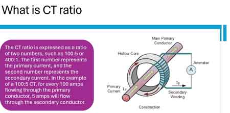
A CT ratio expresses how much primary current is scaled into a standardized secondary output, typically 5A or 1A, so that meters, relays, and protection devices can operate safely and accurately in power systems.
For a broader understanding of device behavior and application, see our main current transformer guide.
Current Transformer Ratio Explained: What You Need to Know
The current transformer ratio (CT ratio) defines the relationship between the primary and secondary currents, allowing high electrical currents to be safely measured for metering, monitoring, and protection in power systems.
A CT ratio expresses how much primary current is scaled down into a standardized secondary output, typically 5A or 1A, so that meters, relays, and monitoring equipment can operate safely and accurately. This scaling process is fundamental to both electrical measurement and system protection.
To understand how ratio selection fits into overall device performance and application, see our main current transformer guide.
Understanding CT Ratio
The current transformer ratio indicates the relationship between the primary and secondary amps, specifying how many primary amps correspond to a specific number of secondary amps. For example, a 300:5 CT means 300 amps on the primary side is reduced to 5 amps on the secondary.
To better understand the device itself, see our overview of what is a current transformer, which explains how CTs operate in high-voltage environments.
This ratio enables electrical meters and relays—designed to handle only low currents—to safely interface with high-current circuits. By converting 100s or even 1000s of amps down to a measurable scale, CTs prevent direct exposure of equipment and personnel to dangerous current levels. For a full breakdown of transformer roles in power systems, visit our guide to electrical power transformers, which includes CTs, PTs, and isolation units.
Sign Up for Electricity Forum’s Electrical Transformers Newsletter
Stay informed with our FREE Electrical Transformers Newsletter — get the latest news, breakthrough technologies, and expert insights, delivered straight to your inbox.
Common CT ratios include:
-
100:5
-
200:5
-
300:5
-
400:5
-
600:5
-
1000:5
Secondary output currents are almost always 5A or 1A, depending on the instrument’s design. Learn more about instrument transformers, a category that includes current transformers and voltage transformers used for metering and protection.
Electrical Transformer Maintenance Training
Substation Maintenance Training
Request a Free Training Quotation
Why the Ratio Matters in Electrical Systems
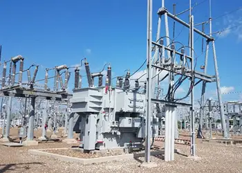
In power distribution systems, current transformers are everywhere—from substations to industrial motor control centers. The CT ratio selected directly affects the accuracy of measurement and the sensitivity of protective relays.
A mismatch between CT ratio and the system current can result in:
-
Inaccurate readings (under- or over-representation of actual current)
-
Delayed or failed tripping by overcurrent protection devices
-
Misleading data in load profiling and energy billing
Understanding and choosing the correct ratio is essential for maintaining both safety and operational efficiency.
Current transformers play a crucial role in electrical measurement and protection. They step down high currents in primary circuits to a manageable level, ensuring that monitoring and protection equipment can safely handle the transformed current. The primary and secondary currents are key elements of this system, working together to maintain accuracy and safety. The current transformer ratio, specifically, refers to the relationship between the primary current in the transformer’s primary conductor and the output in its secondary winding. Proper selection of this ratio ensures the safety and reliability of devices such as meters, relays, and control instruments. If you're looking for a broader understanding of transformer types and applications, check out our article on different types of transformers.
How to Calculate the Current Transformer Ratio
To determine the correct ratio for a specific application, start by understanding the electrical system's needs. Typically, the ratio is calculated by dividing the primary current by the number of secondary amps produced by the transformer. For instance, a 300:5 indicates that for every 300 amps passing through the primary, 5 amps are produced in the secondary winding. Ensuring that the number of turns in the secondary winding supports this relationship is essential for accurate current transformation. This understanding not only protects electrical workers but also enhances system efficiency by providing reliable readings and protection. Discover how CT ratio calculations are integrated into our current transformer simulation tool to model real-world applications.

To calculate the CT ratio:
CT Ratio = Primary Current ÷ Secondary Current
Example:
A CT with a 600:5 rating means 600 amps in the primary results in 5 amps in the secondary. The turns ratio (if 1 primary turn is assumed) is 120:1. This ratio tells us the scaling factor for translating high-voltage current into a usable signal for instruments.
If you pass the primary conductor through the CT core multiple times, you effectively reduce the CT ratio. For example, running the conductor twice through a 100:5 CT changes the effective ratio to 50:5.
This flexibility is useful when CTs with ideal ratings are unavailable or the load profile changes after installation. For high-voltage applications, see how the capacitor voltage transformer compares to current transformers in protection schemes.
CT Accuracy and Burden Ratings
CT performance is defined not just by its ratio, but also by:
-
Accuracy Class – e.g., 0.3, 0.6 for metering; C100, C200 for protection
-
Burden – the total impedance (in ohms or VA) of devices connected to the CT secondary
The Accuracy class defines how closely the secondary output matches the scaled primary input. For instance, a class 0.3 CT has a maximum error of ±0.3 % under the specified burden.
Burden includes the resistance of meter coils and lead wires. If the burden is too high, CTs may saturate, meaning they can't accurately reproduce the current waveform, which can cause false readings or relay failure.
Always select CTs with ratings appropriate to the devices and wire lengths involved.
CT Polarity and Phasing
CT terminals are marked with polarity indicators:
-
H1 / H2: Primary current terminals
-
X1 / X2: Secondary winding terminals
Correct polarity is essential for devices that depend on current direction, such as directional relays or power meters. The current entering H1 should leave from X1 in phase with the primary. Reversing this can cause inaccurate readings or faulty relay operation.
FREE EF Electrical Training Catalog
Download our FREE Electrical Training Catalog and explore a full range of expert-led electrical training courses.

- Live online and in-person courses available
- Real-time instruction with Q&A from industry experts
- Flexible scheduling for your convenience
CT polarity errors are common in installations and can be catastrophic in protection systems. Always double-check orientation.
CT Safety: Never Open the Secondary Under Load
This is a critical rule in electrical safety:
- Never open the CT secondary circuit while the primary is energized.
When the secondary loop is broken while current is flowing in the primary, the core has nowhere to discharge its magnetic energy. This creates dangerously high voltages across the open terminals—often thousands of volts—which can:
-
Damage insulation
-
Destroy connected equipment
-
Electrocute workers
If a CT needs to be removed or tested, always short the secondary first using a shorting block or switch.
Multi-Tap and Multi-Ratio CTs
Modern CTs often offer multiple taps on the secondary winding. These are labelled with selectable ratio options, such as:
-
100:5 / 200:5 / 400:5
-
150:5 / 300:5 / 600:5
Switching between taps allows users to adjust the CT ratio without replacing the transformer. This flexibility is valuable in facilities where loads vary or future upgrades are planned.
Multi-ratio CTs must be properly connected—unused terminals must be insulated, and selected taps must match the expected input to avoid ratio mismatches or damage.
Selecting the Right Ratio for Protection and Metering
Choosing the appropriate current transformer ratio for protection and metering involves evaluating several factors, including load requirements and system voltage. For applications requiring precise metering, a lower ratio may be sufficient, whereas high-voltage protection often requires a higher ratio to safely handle the elevated current levels. The number of secondary windings and the series transformer configuration should align with the system’s demands. For instance, a 100:5 CT might be chosen for a high-current application, allowing only five amps in the secondary while handling 100 amps in the primary. This process often involves selecting a series transformer with the correct number of turns in both primary and secondary windings. You can also explore how CTs relate to the cousin control transformer, which manages voltage regulation for control circuits in electrical systems.
Why CT Ratio Knowledge Matters
The current transformer ratio is not just a number—it's the backbone of scaling for every power monitoring and protection system. Whether you’re an electrician, engineer, or technician, understanding CT ratios helps you:
-
Prevent equipment damage
-
Ensure accurate billing
-
Protect systems from faults
-
Maintain compliance with standards
Choosing the correct ratio, validating polarity, accounting for burden, and observing safety procedures will ensure your power systems remain accurate, safe, and efficient.
Related Articles
