VFD Sizing - Motor Selection Factors
By Paul Wright, P.Eng.
VFD Training
Our customized live online or in‑person group training can be delivered to your staff at your location.
- Live Online
- 12 hours Instructor-led
- Group Training Available
Download Our OSHA 3875 Fact Sheet – Electrical PPE for Power Industry Workers
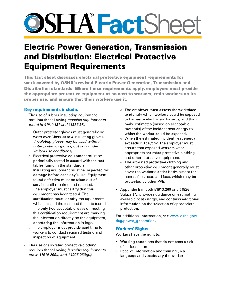
- Follow rules for rubber gloves, arc-rated PPE, and inspection procedures
- Learn employer obligations for testing, certification, and training
- Protect workers from arc flash and electrical shock injuries
VFD sizing is the engineering decision of selecting a drive whose continuous and intermittent current ratings match a motor’s real operating load, torque profile, and site conditions so that overheating, nuisance tripping, and premature equipment failure are avoided, requiring designers to rely on motor nameplate current, application torque behavior, and overload duty rather than horsepower alone.
How VFD Sizing Controls Motor Reliability
Correct VFD sizing determines whether a motor operates within its electrical and thermal limits or gradually degrades under hidden stress. Engineers must evaluate full-load amperage, torque characteristics, overload capacity, duty cycle, and environmental conditions to ensure the selected drive can supply stable current across all operating scenarios. When these factors are ignored, variable frequency drive sizing errors lead to insulation damage, nuisance faults, and unpredictable system downtime.
VFD Selection Criteria
VFD sizing begins with the motor's full-load amperage, but a professional selection quickly moves beyond nameplate values. Constant-torque applications, such as positive-displacement pumps and conveyors, impose sustained current and torque demands that differ fundamentally from those of variable-torque loads, such as fans and centrifugal pumps. Drives must be sized to handle these torque profiles without exceeding thermal or electrical limits across the entire speed range.
Environmental conditions further influence sizing decisions. High altitude reduces cooling effectiveness, while elevated ambient temperatures reduce continuous current capability. These factors explain why experienced designers validate drive selection using both manufacturer-derating guidance and real operating margins, rather than relying solely on catalog current ratings.
Proper VFD sizing
Proper VFD sizing protects motors and drives from long-term electrical stress that may not appear during commissioning. Drives that operate too close to their current limits experience accelerated component aging, unstable control performance, and increased susceptibility to nuisance trips. Correct sizing preserves insulation life, stabilizes torque delivery, and maintains predictable motor behavior over time. When considering Variable Frequency Drive sizing, it's also important to understand how different VFD drives operate and the impact they have on motor control performance.
Electricity Today T&D Magazine Subscribe for FREE

- Timely insights from industry experts
- Practical solutions T&D engineers
- Free access to every issue
Because horsepower ratings alone do not reflect electrical demand, variable frequency drive sizing must always be based on the motor's nameplate current. Motors with identical horsepower ratings can draw significantly different currents depending on efficiency, winding design, and service factor. Using current as the primary sizing reference ensures the drive can continuously supply the required load without thermal overload or control instability.
In VFD Sizing, the main considerations are:
Continuous Current: The Variable Frequency Drive's continuous current shall be higher than the motor’s current at maximum load. It is not necessary to size the Variable Frequency Drive to the motor's Full Load Amps (FLA) rating if the motor is oversized for the application. A motor that operates under worst-case conditions at 80% FLA current flowing only requires a Variable Frequency Drive that can continuously supply this 80% current value.
Intermittent Current: For Variable Torque Applications, the intermittent current shall be 115% greater than the motor current rating for the worst-case starting scenario. If the motor rated current is 65 amperes, then the intermittent current rating should be greater than 74.8 amperes (65A x 115%).
Constant Torque: For Constant Torque Application, the intermittent current shall be 150-200% of the motor's rated current. The equipment OEM can provide the actual worst-case starting torque that they would normally expect for the application. By ensuring that the Variable Frequency Drive's intermittent current capability exceeds this value, the ac drive will produce sufficient torque to start the HP motor under abnormal conditions. Accurate VFD programming ensures that a properly sized drive operates within the correct voltage and current limits, protecting connected equipment.

Single-phase input voltage tolerance
The single-phase input voltage tolerance rating for the Variable Frequency Drive shall be higher than the highest line voltage and lower than the lowest line voltage that persists for more than two seconds in the facility. Variable Frequency Drives have a 100% voltage rating of 200, 230, 460 or 575 Volts. Each site has different high and low line levels that the Variable Frequency Drive must be able to safely operate at without being damaged.
If the measured low line voltage is 550 volts and the high line voltage is 625 volts, then we need a 575-volt-rated Variable Frequency Drive with a voltage tolerance of 575 volts plus 10.9% (625 volts), minus 4.6% (550 volts), or greater. Actual common tolerance values for Variable Frequency Drives are as follows: -5 %, 10%, 12%, 15%, and 20%. Some 575v commercial-rated Variable Frequency Drives are 575v +5%, -10% (518v to 603v), whereas an industrial-rated Variable Frequency Drive may be rated 575v +/- 15% (489v to 660v).
If the Variable Frequency Drive's tolerance rating does not meet the high-line, actual site-voltage condition, it is subject to catastrophic failure. In some cases, a frequency converter may be necessary in conjunction with a Variable Frequency Drive to manage input or output frequencies that affect proper sizing.
Other Variable Frequency Drive equipment to be upgraded or changed:
Many factors need to be considered when conducting VFD sizing in an existing application:
-
Is the existing motor suitable for the speed range, and is the insulation designed to withstand dv/dt stress from the fast switching of the voltage pulses to the motor? If not, use a NEMA MG1 Part 31 designed motor.
-
All VFD manufacturers recommend replacing the motor feeder cable with a shielded, symmetrical cable.
Motor specifications
In North America, NEMA MG1 standards are used to specify motors. In 1992, a new section (Part 31) was added to specifically address the motor design requirements for use in a Variable Frequency Drive application without installing motor feeder filtering. The original Part 30 design motor nameplate specification allowed for Variable Frequency Drive (VFD) operation if properly sized motor filters were installed in the VFD package.
Test Your Knowledge About Motors and Drives!
Think you know Motors and Drives? Take our quick, interactive quiz and test your knowledge in minutes.
- Instantly see your results and score
- Identify strengths and areas for improvement
- Challenge yourself on real-world electrical topics
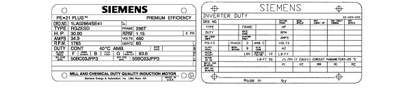
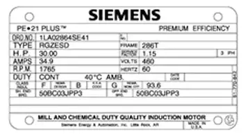
Figure 1: NEMA Part 30 & 31 Nameplates
Since each application required a custom-engineered solution for proper motor filter selection, most users and Variable Frequency Drive distributors were not qualified to select the filters properly, thereby increasing the risk of improper filter selection. By installing the NEMA MG1 Part 31 designed motor, there is no requirement to install a motor filter. The deletion of the requirement for a motor filter typically offsets the slight cost increase associated with the Part 31 motor. The Part 31 motor has an enhanced nameplate that provides motor performance data for the lowest operating speed, the base 60Hz speed, and the highest speed above 60Hz.
System component used with Variable Frequency Drives:
A Variable Frequency Drive does not operate in isolation. Long-term reliability depends on the supporting electrical system provided with the drive. Circuit breakers must coordinate with drive protection characteristics. Surge protection limits transient damage. Line reactors and harmonic filters stabilize current quality and reduce component stress. Cable selection controls reflected wave effects and insulation degradation.
Motor compatibility is equally critical. NEMA MG1 Part 31 motors are designed to withstand the voltage rise times and switching stress imposed by modern drives. Ambient temperature and enclosure ventilation must also be considered, as thermal derating directly affects allowable current capacity. VFD sizing decisions that ignore these supporting elements often appear correct on paper but fail in service.
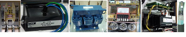
Figure 2: Circuit breaker, MOVs, Reactor, Harmonic Filter, and Variable Frequency Drive Cable
For Variable Frequency Drives used in building systems, review the special considerations outlined in Variable Frequency Drive HVAC applications.
Additional VFD Design and Application References
