Fault Current Calculation Explained
Protective Relay Training - Basic
Our customized live online or in‑person group training can be delivered to your staff at your location.

- Live Online
- 12 hours Instructor-led
- Group Training Available
Download Our OSHA FS3529 Fact Sheet – Lockout/Tagout Safety Procedures

- Learn how to disable machines and isolate energy sources safely
- Follow OSHA guidelines for developing energy control programs
- Protect workers with proper lockout devices and annual inspections
Fault current calculation determines the maximum current that can flow during a short-circuit condition and whether protective devices will interrupt it without failure. In electrical protection engineering, this value defines the boundary between controlled fault clearing and equipment failure.
Designers rely on fault current values to confirm that circuit breakers, fuses, relays, and bus structures are mechanically and thermally capable of surviving worst-case fault conditions. If available fault current is underestimated, protective devices may fail to interrupt. If it is overestimated, systems may be over-designed and unnecessarily costly. In both cases, system reliability is compromised.
For this reason, fault current calculation is not a theoretical exercise. It is a core input for short-circuit studies, protective device coordination, equipment rating verification, and code-compliance documentation. Every electrical system, from small distribution panels to utility substations, depends on accurate fault-current data to maintain safe, predictable operation.
Fault current values are formally documented as available fault current so inspectors, engineers, and equipment suppliers can verify that protection devices are correctly rated.
This article explains how fault current is calculated, how different fault conditions influence magnitude, and why these calculations are central to modern electrical protection design.
The Importance of Fault Current Calculation
Fault current calculation is a foundational input to modern electrical protection system design, because it defines the maximum stress that protection equipment must withstand and interrupt during abnormal conditions.
Fault current calculations are typically performed as part of a short-circuit analysis and then applied to protective device coordination to verify that breakers, fuses, and relays will interrupt fault currents within their rated limits.
FREE EF Electrical Training Catalog
Download our FREE Electrical Training Catalog and explore a full range of expert-led electrical training courses.

- Live online and in-person courses available
- Real-time instruction with Q&A from industry experts
- Flexible scheduling for your convenience
Fault current calculation sits within the broader discipline of electrical protection, where system design focuses on controlling abnormal electrical conditions before they damage equipment or endanger personnel.
Why is Fault Current Calculation Important?
A short-circuit current calculation determines the amount of current that flows through an electrical system during an abnormal condition. These conditions can occur when conductors make unintended contact, causing an unimpeded surge of current. Such events pose significant risks and can lead to equipment damage, fires, and personal injury.
Accurate calculations allow engineers to verify that protection devices can interrupt the maximum available current without mechanical or thermal failure. These devices must be capable of interrupting the available prospective current to prevent failures and ensure compliance with safety standards such as the National Electrical Code (NEC). For example, NEC 110.24 mandates that the available short-circuit current at service entrance equipment be labeled. This requirement ensures safe operation and proper protection.
Results from fault studies directly influence the selection and application of circuit protection devices with adequate interrupting ratings.
How is Fault Current Calculated?
Fault current calculation involves determining the short-circuit level at various points in the system. This requires knowledge of full-load current, the impedance of conductors, transformers, and other components. Engineers use mathematical formulas or specialized software to perform these studies.
These calculations form the technical basis for short-circuit protection and coordinated interruption planning.
Accurate values also influence the proper rating and application of fuse types, which protect conductors from excessive thermal and mechanical stress.
Basic Fault Current Calculation Principles
At the simplest level, short-circuit current can be understood using Ohm’s Law:
I = V ÷ R
Here, system voltage (V) is divided by circuit resistance (R). While this illustrates the concept, real-world systems also include reactance, making total impedance the governing factor.

Three-Phase Fault Current Calculation Formula
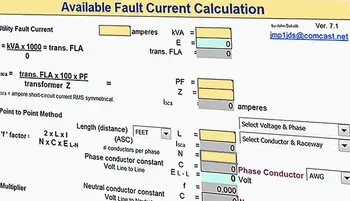
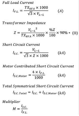
For practical applications, engineers often use a transformer-based calculation:
Fault Current (A) = (kVA × 1000) ÷ (√3 × Voltage) ÷ (%Z ÷ 100)
This formula estimates the prospective short-circuit current at a transformer’s secondary, based on its kVA rating, operating voltage, and impedance. It provides a more accurate reflection of the levels protective devices must handle.
Maximum Fault Current Calculation
Maximum fault current calculation determines the highest prospective short-circuit current that can occur at a specific point in the electrical system under worst-case conditions. This value governs whether circuit breakers, fuses, switchgear, and bus structures can survive the initial fault without mechanical or thermal failure.
While general fault current calculations establish expected operating values, the maximum fault current calculation defines the upper limit that protective equipment must safely interrupt. Engineers evaluate this condition using the lowest possible system impedance, full source contribution, and transformer impedance tolerances that favor maximum current flow.
The maximum fault current is most critical at service entrances, transformer secondaries, main switchboards, and motor control centers, where interrupting and withstand ratings are directly governed by this value.
If the maximum fault current is underestimated, protective devices may fail catastrophically during the first half-cycle of a fault. If it is overestimated, equipment may be oversized, increasing costs without improving safety. Accurate maximum fault-current calculation, therefore, controls both protection reliability and design efficiency.
In practice, engineers determine maximum fault current by:
• Using transformer minimum impedance values.
• Assuming full upstream utility contribution.
• Minimizing conductor length and resistance effects.
• Evaluating three-phase bolted fault conditions.
The resulting value represents the maximum electrical stress the system can withstand. All interrupting ratings, momentary withstand ratings, and peak let-through limits must be verified against this condition.
Sign Up for Electricity Forum’s Electrical Protection Newsletter
Stay informed with our FREE Electrical Protection Newsletter — get the latest news, breakthrough technologies, and expert insights, delivered straight to your inbox.
Maximum fault current calculation is therefore not a separate discipline from fault current calculation. It is the limiting case that determines whether the protection system will survive its most extreme operating condition.
Symmetrical vs. Asymmetrical Fault Currents
-
Symmetrical current is the steady-state sinusoidal current after the DC offset decays.
-
Asymmetrical current includes the initial DC offset, resulting in higher peak currents during the first few cycles.
This distinction is critical for specifying protective relays and breakers that must tolerate both peak and steady-state conditions.
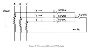
Types of Faults
Faults differ in severity and current magnitude depending on how conductors and ground are involved:
-
Line-to-Ground – The most common, involving a single phase conductor and ground.
-
Line-to-Line – Two conductors come into contact, producing larger currents than single line-to-ground.
-
Double Line-to-Ground – Two conductors contact ground simultaneously.
-
Three-Phase – The most severe, creating the highest short-circuit current levels.
Complex systems rely on relay and circuit breaker coordination to ensure faults are isolated without unnecessary upstream outages.
Broader Benefits of Short Circuit Studies
Short-circuit studies are not limited to device sizing—they provide additional benefits:
-
Voltage depression analysis to protect sensitive loads.
-
Mechanical stress evaluation for conductors and busbars.
-
System reliability assurance by identifying and mitigating weak points.
-
Equipment design and maintenance planning to match ratings with real-world conditions.
Fault current data also supports transformer protection by confirming that windings and insulation remain within safe limits during fault events.
Short-circuit results also guide overcurrent protection and the application of overcurrent relays.
Software Tools and Standards
Today, current analysis is supported by advanced software that enables engineers to model complex systems, calculate available short-circuit currents, and coordinate protection devices efficiently.
Guidance is also available from global standards, including:
-
IEEE 1584 – Arc flash and current analysis
-
IEC 60909 – International short-circuit calculation standard
-
NFPA 70E – Electrical safety and compliance requirements
Fault current values are also required when specifying metal-clad switchgear for mechanical fault withstand ratings.