Single Phase Arc Flash Calculations Explained
By Harold WIlliams, Associate Editor

NFPA 70E Training
Our customized live online or in‑person group training can be delivered to your staff at your location.

- Live Online
- 6 hours Instructor-led
- Group Training Available
Download Our OSHA FS3529 Fact Sheet – Lockout/Tagout Safety Procedures

- Learn how to disable machines and isolate energy sources safely
- Follow OSHA guidelines for developing energy control programs
- Protect workers with proper lockout devices and annual inspections
Single phase arc flash calculations estimate arcing current, incident energy, and arc flash boundary for 120/240 V and MV equipment. The main drivers are clearing time, working distance, and whether the arc can sustain in open air or an enclosure.
Understanding Single Phase Arc Flash Calculations
Most people come to single-phase arc flash because something in the field feels slightly unresolved. A 120/240 V panelboard is being labeled, a single-phase UPS bypass cabinet is in scope, a control power transformer is feeding a crowded enclosure, or a site has a lot of line-to-neutral work that never shows up cleanly in the three-phase mental model.
Before touching an equation, the practical question is simple: can an arc in this configuration realistically sustain, and if it does, will the protective device let it live long enough to matter? If the answer is “no,” precision is not the victory people think it is. If the answer might be “yes,” then you want a method that is transparent about assumptions and conservative in a way you can explain.
Request a Free Training Quotation
This approach is meant for AC single-phase arcs where you have enough information to describe the source, the conductor gap, and the likely clearing behavior of the upstream device. It can be used for open-air conditions and for enclosed equipment, but it does not settle every edge case. Very low-voltage arcs, unusual electrode geometry, poor maintenance, and “unknown” protective behavior can dominate outcomes, and at that point the inputs are the story, not the formula.
ARCING CURRENT
Single-phase work gets tricky because the arc is not a short circuit, it is a non-linear load. The plasma introduces an effective resistance, the system sees it through the source X/R, and the result is that arcing current can land far enough below bolted fault current to change how the upstream device responds.
FREE EF Electrical Training Catalog
Download our FREE Electrical Training Catalog and explore a full range of expert-led electrical training courses.

- Live online and in-person courses available
- Real-time instruction with Q&A from industry experts
- Flexible scheduling for your convenience
Voltage drop Varc across the equivalent arc resistance can be expressed as:
Varc = -I * Rs + (Vs2 - I2 * Xs2)1/2
Equation 1
Where I is current in Amps, Vs is the open-circuit voltage in Volts, and Rs and Xs are the system resistance and reactance, including the source and feeders.
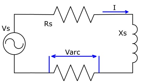
Figure 1. Single & three-phase AC arc flash equivalent circuit.
A detail that matters more than people expect is the “will it even hold” question. A minimum current is needed to maintain an arc, and that transitional point depends on the conductor gap:
It = 10 + 0.2 * G
Equation 2
Where G is gap distance in millimetres, and It is in Amps.


Above that minimum, the arc V-I characteristic can be expressed as:
Varc = (20 + 0.534 * G) * Iarc0.12
Equation 3
Or rearranged:
Iarc = [Varc / (20 + 0.534 * G)]8.33
Equation 4
In practice, you solve for the operating point where the arc characteristic crosses the circuit load line. The iteration does not need to be complicated to be useful. Start with a reasonable guess for Iarc (many engineers begin near half the available bolted fault current), compute Varc from Equation 1, update Iarc using Equation 4, and repeat until the values stop moving in a meaningful way. If the iteration tries to run away or collapses to an unphysical result, that is not a math failure. It is often a sign that the assumptions about gap, source impedance, or sustainability need to be revisited.
A note on “the familiar IEEE 1584 route”
Many workplaces still use the three-phase IEEE 1584 framework with single-phase bolted fault current as an intentionally conservative proxy. That can be a reasonable program choice, but it should be treated as a documented approximation, not a hidden shortcut. Conservative results are not always safer in the real world if they drive PPE levels that people stop following or labels nobody trusts. If you do use a conservative proxy, say so plainly on the label notes and in the study file.
POWER AND ENERGY IN THE ARC
Once you have an arcing current that you are willing to stand behind, the rest of the calculation becomes a story about time. Incident energy is rarely “high” because of voltage alone. It is high because an arc is allowed to exist, and protection does not end it quickly.
Test Your Knowledge About Arc Flash!
Think you know Arc Flash? Take our quick, interactive quiz and test your knowledge in minutes.
- Instantly see your results and score
- Identify strengths and areas for improvement
- Challenge yourself on real-world electrical topics
Power in the arc:
Parc = Iarc * Varc
Equation 7
Energy in the arc:
Earc = Parc * tarc
Equation 8
For open-air conditions (radiant heat assumption), incident energy at distance D:
Eiair = Earc / (4 * π * D2)
Equation 9
This is conservative because it treats all arc energy as radiant heat, even though some energy goes into pressure rise and electrode heating.
For enclosed equipment (arc-in-a-box), the enclosure focuses energy toward the worker. For the selected enclosure type and test distance:
Eibox = K * Earc / (A2 + D2)
Equation 10
Worked example, not a sales pitch
Consider a 120/240 V single-phase cabinet where a 25 mm conductor gap is a reasonable approximation for the exposed spacing at the point of concern. Suppose your iteration lands near Iarc ≈ 2.0 kA and Varc ≈ 83 V (values that are consistent with the arc V-I form above for that gap).
That yields Parc ≈ 166 kW.
Now look at two clearing-time cases, because that is where reality usually hides:
Case 1, fast clearing (0.10 s):
Earc ≈ 16.6 kJ
At 45 cm working distance, Eiair ≈ 0.653 J/cm2, which is about 0.156 cal/cm2 (1 cal/cm2 = 4.184 J/cm2)
Case 2, slower clearing (0.30 s), for example because arcing current sits below instantaneous pickup:
Earc ≈ 49.8 kJ
At 45 cm, Eiair ≈ 1.96 J/cm2, about 0.468 cal/cm2
The numbers are not the headline here. The headline is that the same equipment can look tame or meaningful depending on what the protective device actually does at the arcing current, not the bolted fault current.
ARC FLASH BOUNDARY
The boundary is simply the distance where the chosen threshold energy is met.
From the open-air form:
AFB = [Earc / (4 * π * Et)]0.5


Equation 11
Threshold incident energy to second degree burn:
Et = 5 * t0.3
Equation 12
For arc-in-a-box:
AFB = [K * Earc / Et - A2]0.5
Equation 13
Using the worked example above, and keeping the same two clearing-time cases:
At 0.10 s:
Et ≈ 2.51 J/cm2
AFB ≈ 23.0 cm
At 0.30 s:
Et ≈ 3.48 J/cm2
AFB ≈ 33.7 cm
That boundary is what ends up on labels, but the assumptions are what keep labels defensible. If you cannot explain the clearing-time logic, you do not really have a boundary; you have a guess.
A few reality checks before you trust the output
If Iarc is below the instantaneous region, stop and treat time as uncertain until you verify the curve and settings. This is where single-phase results often surprise people.
Run the calculation at two plausible clearing times. If the decision flips, your program needs to document which case governs and why.
Be explicit about open air versus enclosure. The enclosure term is not a nuance, it can dominate exposure.
Write down the working distance you used and why it makes sense for the task. “18 inches” is common, but not universal, and small changes have visible effects.
Utility and overhead open-air single-phase to ground, a different conversation
If you are dealing with overhead distribution, open-air single-phase-to-ground events, or utility switching work, be careful about mixing models. Utility practice often relies on different assumptions and tools, and the physics of open-air arcs and worker positioning changes the exposure picture. Treat that scenario as its own study problem rather than forcing it into a cabinet-style enclosure framework.
Related Articles
