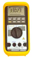
How to Use a Digital Multimeter
NFPA 70b Training - Electrical Maintenance
Our customized live online or in‑person group training can be delivered to your staff at your location.

- Live Online
- 12 hours Instructor-led
- Group Training Available
Download Our OSHA 3875 Fact Sheet – Electrical PPE for Power Industry Workers
- Follow rules for rubber gloves, arc-rated PPE, and inspection procedures
- Learn employer obligations for testing, certification, and training
- Protect workers from arc flash and electrical shock injuries
Digital multimeters are used to measure AC and DC voltage, current, and resistance, check continuity, select measurement ranges, and troubleshoot electrical circuits safely and accurately in real-world applications.
Understanding Digital Multimeters
Digital multimeters are indispensable tools in electrical work, not because they are complex, but because they allow problems to be isolated quickly when used with judgment. With a wiring diagram and a basic understanding of what the meter is telling you, most faults can be narrowed down without guesswork. The key is not just knowing which function to select, but understanding how the meter interacts with the circuit under test.
Although digital meters have replaced analog multimeters in most applications, their behavior still reflects the same electrical principles. Knowing how and when to measure voltage, current, or resistance, and just as importantly, when not to, separates reliable testing from misleading readings and damaged equipment.
This article focuses on the practical use of a digital multimeter in real electrical systems, emphasizing technique, interpretation, and common pitfalls rather than step-by-step instructions.
Typical Amperage Test
Measuring current requires more care than most other tests because the meter becomes part of the circuit. When inserted incorrectly or set to the wrong range, a current test can blow a fuse, damage the meter, or disrupt the system being tested. Even with modern digital multimeters, internal resistance and meter burden can influence sensitive electronic circuits.
Before measuring amperage, it is worth pausing to consider what you expect to see. Is the circuit lightly loaded or near its operating limit? Are you measuring milliamps in a control circuit or full load current in a power circuit? Many meters offer autoranging, but autoranging does not replace awareness. Misreading milliamps as amps, or overlooking the meter’s current rating, remains a common cause of equipment failure. You could mistake 10 mA for 10 amps. Evaluating meter burden and circuit behavior is part of sound electrical testing practice to prevent misleading readings and component stress.
Test Your Knowledge About Test Equipment!
Think you know Test Equipment? Take our quick, interactive quiz and test your knowledge in minutes.
- Instantly see your results and score
- Identify strengths and areas for improvement
- Challenge yourself on real-world electrical topics
Good practice is to start with the highest safe range, confirm lead placement, and refine the measurement only if needed. When readings seem inconsistent across ranges, structured electrical troubleshooting steps can isolate whether the issue is technique, setup, or a faulty component.
Typical Voltage Test
Voltage testing is often the safest and most informative place to begin troubleshooting. Because voltage measurements place minimal load on the circuit, they allow you to confirm supply conditions without altering circuit behavior.
Digital multimeters display voltage with decimal precision, which makes accuracy easy but also invites mistakes. A misplaced decimal point can change the meaning of a reading entirely. For this reason, readings should always be interpreted in context. If a value looks wrong, verify the range and reference point before concluding.
Voltage testing is most effective when done methodically. Confirm the source first, then work outward toward the load. Unexpected drops often reveal loose connections, undersized conductors, or failing components long before visible damage appears.
Typical Resistance Test
Resistance testing relies on the meter’s internal battery, which means the circuit must be completely de-energized. Attempting to measure resistance on a live circuit risks damaging the meter and producing meaningless results. For insulation checks on cables and windings, an insulation resistance tester supplies a controlled DC test voltage to reveal leakage paths reliably.
In practice, resistance tests are used to identify opens, shorts, and abnormal values rather than to confirm exact resistance under operating conditions. A zero reading indicates a short, while an infinite reading suggests an open circuit. Components that fall between those extremes require interpretation. Experience matters here. A reading that technically falls within specification may still indicate deterioration when compared to previous measurements.


Comparing results over time using an electrical insulation resistance test procedure helps detect gradual moisture ingress or degradation before failure. For very high resistance values or insulation checks, a standard digital multimeter may not be sufficient. In those cases, dedicated megohmmeter provides more reliable insight than forcing a general-purpose meter beyond its intended use.
Before condemning a part as open or shorted, follow best practices for checking insulation resistance to account for lead placement, temperature, and stabilization time.
Related Articles

