Electrical Insulator Explained
By R.W. Hurst, Editor
Download Our OSHA FS3529 Fact Sheet – Lockout/Tagout Safety Procedures
- Learn how to disable machines and isolate energy sources safely
- Follow OSHA guidelines for developing energy control programs
- Protect workers with proper lockout devices and annual inspections
Electrical insulator materials resist current flow to protect people and equipment. Used in power transmission and switchgear, electrical insulators rely on high resistivity, dielectric strength, and breakdown voltage to prevent leakage.
Electric power only works when it stays inside its intended path. An electrical insulator exists to make sure it does. Unlike conductors, which are chosen to carry current, it is chosen because it prevents current from passing.
In real systems, an electrical insulator separates energized components from grounded structures, confines electric fields within equipment, and prevents accidental discharge. When insulation fails, electricity does not quietly drift. It escapes violently, often in the form of arcing, flashover, or short-circuit faults.
An electrical insulator does not conduct electricity. It confines it.
They are a foundational component of modern electric power distribution networks, where controlled isolation is as critical as energy delivery.
How an Electrical Insulator Works
An electrical insulator does not stop electricity in a mechanical sense. It works because its internal structure resists the formation of a conductive path. Electrons remain tightly bound, even when an electric field is applied, which prevents charge from moving freely through the material.
Three properties define this behaviour in practice: resistivity, dielectric strength, and breakdown voltage. Together, they describe the amount of stress a material can withstand before it begins to conduct. Engineers rely on these characteristics when selecting materials for transmission and distribution systems, where failure is not theoretical but inevitable if margins are misjudged. High-voltage insulation performance is especially critical along electricity transmission corridors, where fault consequences are magnified.
FREE EF Electrical Training Catalog
Download our FREE Electrical Training Catalog and explore a full range of expert-led electrical training courses.

- Live online and in-person courses available
- Real-time instruction with Q&A from industry experts
- Flexible scheduling for your convenience
A high-quality electrical insulator is therefore not simply non-conductive. It is predictably non-conductive under known power, thermal, and environmental conditions.
Where Electrical Insulators Are Used
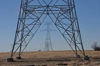
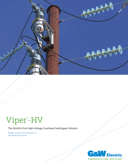
Electrical insulators appear anywhere voltage must be supported without conduction. In overhead transmission lines, conductors are held above grounded towers. Inside substations, they isolate buswork, breakers, and transformers. In cables and equipment, insulating layers prevent unintended current paths between live components and surrounding structures.
Their role becomes especially evident along long-span transmission lines, where mechanical loading and stress coexist.
In many cases, the insulator is the only barrier between controlled energy and equipment destruction.
Materials Used in Electrical Insulators
Porcelain and glass dominated early transmission systems and remain in service worldwide. Porcelain offers mechanical stability but adds weight and brittleness. Glass provides excellent dielectric strength but can be affected by surface moisture and internal stress. Composite materials are widely used in modern protection equipment because their insulating properties remain stable.
Composite polymer electrical insulators introduced a different balance. Silicone rubber housings over fibreglass cores reduced weight and improved pollution performance. In coastal and industrial regions, these materials often outperform traditional ceramics. Long-term aging, however, remains an important design consideration. Modern utilities continue to evaluate alternatives such as glass electrical insulators for specific environmental and mechanical conditions.
No electrical insulator material is perfect. Each represents a compromise between behaviour, durability, and environmental resistance.
Electrical Insulators in High-Voltage Transmission
High-voltage transmission places extreme demands on electrical insulators. Porcelain electrical insulators are formed from clay, quartz or alumina, and feldspar, then glazed to reduce surface contamination. Alumina-rich porcelain provides higher mechanical strength, while dielectric strength typically ranges between 4 and 10 kV per millimetre.
Glass electrical insulators offer higher dielectric strength but tend to attract condensation, requiring thicker shapes that introduce internal stresses. These issues led many manufacturers to replace glass designs with ceramic alternatives in the late twentieth century.
Composite polymer electrical insulators use a fibreglass core with a silicone rubber or EPDM outer housing. Their hydrophobic surfaces perform well in polluted environments and their lighter weight simplifies installation. Long-term aging performance remains a key evaluation factor.
These designs are now common on modern AC transmission lines, where contamination and vibration exposure are constant.
Electrical Insulator Breakdown and Failure
Every electrical insulator has a limit. When voltage stress exceeds its breakdown strength, the material no longer resists current. Once that threshold is crossed, the insulator becomes part of the circuit it was meant to isolate.
Contamination, moisture films, surface damage, and aging accelerate this process. That is why insulator shape, creepage distance, and surface design are just as important as material selection in high-voltage systems. Effective insulation performance is tightly linked to reliability and protection in utility distribution programs.
Electrical insulators are designed not only to resist current, but to delay failure as long as possible under real operating conditions.
Types of Electrical Insulators in Power Lines
Pin Insulator - This type is attached to a pin mounted on a utility pole's cross-arm. It features a groove near its top, just below the crown, through which the conductor runs and is fastened using an annealed wire made of the same material as the conductor. Pin insulators are commonly used to transmit communication signals and electric power at voltages of up to 33 kV. However, they can become bulky and uneconomical for operating voltages between 33 kV and 69 kV.
Post Insulator - Introduced in the 1930s, they are more compact than traditional pin-types. They have rapidly replaced many pin types in lines with voltages up to 69 kV and, in some configurations, can be designed for operation up to 115 kV.
Sign Up for Electricity Forum’s Overhead T&D Newsletter
Stay informed with our FREE Overhead T&D Newsletter — get the latest news, breakthrough technologies, and expert insights, delivered straight to your inbox.
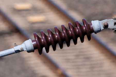
Suspension Insulator - Suspension devices are typically utilized for voltages exceeding 33 kV. They consist of a series of glass or porcelain discs linked together with metal connectors, forming a string. The conductor is suspended from the bottom of this string, while the top is secured to the tower's cross-arm. The number of disc units required depends on the voltage.
Strain Insulator - When a straight section of a transmission line ends or changes direction, a dead-end or anchor pole or tower is employed. These structures must withstand the lateral (horizontal) tension from the long straight section of wire. Strain devices are used to support this load. For low-voltage lines (under 11 kV), shackle ones are strain insulators. For high-voltage transmission lines, cap-and-pin (suspension) insulator strings are used, mounted horizontally to the crossarm. In cases of extremely high tension, such as long river spans, two or more parallel strings may be necessary.
Shackle Insulator - Initially, shackle types were employed as strain insulators. Nowadays, they are predominantly used for low-voltage distribution lines. These can be installed in horizontal or vertical orientation and can be directly fastened to the pole with a bolt or to the crossarm.
Each type exists because field conditions demanded a specific solution.
Selecting the Right Electrical Insulator
Choosing an insulator is rarely about maximizing specifications. It is about matching voltage, environment, mechanical load, and maintenance reality. A desert transmission line, a coastal substation, and an urban distribution pole each impose different stresses.
The best electrical insulator is not the one with the highest rating. It is the one that still performs after years of exposure.
They rarely receive attention when they work correctly. Yet every stable power system depends on them. They do not move electricity forward. They quietly keep it where it belongs.
Related Articles
