Electrical Distribution System
By Howard Williams, Associate Editor
Download Our OSHA 3875 Fact Sheet – Electrical PPE for Power Industry Workers
- Follow rules for rubber gloves, arc-rated PPE, and inspection procedures
- Learn employer obligations for testing, certification, and training
- Protect workers from arc flash and electrical shock injuries
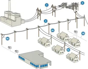
Electrical Distribution System is the part of the power grid where high-voltage transmission energy is converted, controlled, and delivered as usable electricity to homes, businesses, and industrial facilities through transformers, feeders, switches, and protective equipment. It is the stage where grid reliability, safety, and performance are either preserved or quietly compromised.
When a distribution system is misunderstood or poorly designed, problems rarely appear as immediate failures. Instead, they surface as voltage instability, recurring outages, equipment stress, protection miscoordination, and long-term reliability loss that is difficult to trace back to a single cause. What looks like a local fault is often a distribution design consequence.
This is why electrical distribution is not just an infrastructure topic. It is a decision framework. Choices about feeder routing, transformer placement, sectionalizing points, and protection coordination determine how safely power is delivered, how faults are contained, and how easily a system can adapt to growth, renewable integration, and changing load behavior.
For engineers, utilities, and facility designers, the electrical distribution system defines the boundary between theoretical grid capacity and real operational performance. It is where planning becomes accountability.
Electrical Distribution System Operation and Structure
Electricity does not move directly from generation plants into usable circuits. It passes through the electrical distribution system, where voltage is reduced, flow is controlled, and protection is applied before energy enters buildings and equipment. This is the stage where bulk transmission power becomes practical, usable electricity.
Distribution begins at substations and ends at service entrances. Along that path, transformers regulate voltage, feeders carry load, switches control routing, and protective devices isolate faults. When these elements are correctly coordinated, the system operates quietly. When they are not, outages, damage, and safety risks follow.
FREE EF Electrical Training Catalog
Download our FREE Electrical Training Catalog and explore a full range of expert-led electrical training courses.

- Live online and in-person courses available
- Real-time instruction with Q&A from industry experts
- Flexible scheduling for your convenience
Distribution design is shaped by environment and purpose. Rural systems prioritize reach and economy. Urban networks emphasize redundancy and restoration speed. Industrial systems require isolation control, fault tolerance, and predictable behavior. These realities explain why no two electrical distribution systems are identical, even when they serve similar loads.
At its core, the electrical distribution system serves as the interface between the grid and everyday electrical use. Understanding how it functions is essential for anyone responsible for system reliability, safety, and long-term performance.
The backbone of reliable supply depends on electricity transmission seamlessly connecting with local distribution systems to deliver power where it’s needed.
Electrical Distribution System Topologies
How a distribution system is laid out has real consequences. Reliability, restoration time, operating cost, and maintenance effort are all shaped by topology decisions made early in design. In practice, engineers do not select a layout because it looks good on paper. They select it based on load density, customer expectations, and the amount of downtime the system can tolerate when something goes wrong.
Most distribution systems fall into one of three general arrangements: radial, loop, or network. Each has strengths and limitations, and no single topology works best in every situation. Understanding these differences explains why rural feeders are typically simple, while urban and industrial systems are not.
Radial Distribution Systems
Radial distribution is the simplest and most widely used topology. Power flows outward from a single substation through feeders to end users, with no alternate supply path under normal operation. This approach is common in rural areas and small communities where load density is low, and cost control matters more than redundancy.


In practice, radial feeders are easy to design and maintain, which is why utilities continue to use them extensively. The drawback is straightforward: when a fault occurs on a feeder, every customer downstream loses power until repairs are completed. For areas where outages are acceptable and restoration time is not mission-critical, this trade-off is usually reasonable.
Loop Distribution Systems
Loop, or ring-type, systems are used when service continuity becomes more important. Feeders are arranged in a closed loop, but only one section is energized at a time. If a fault occurs, the affected segment can be isolated and power restored from the opposite direction.
What matters most here is flexibility. Loop systems allow utilities to reroute power quickly without rebuilding infrastructure. They are commonly found in commercial districts and medium-density residential areas, especially where outages have a measurable economic impact. The added equipment and control requirements raise installation cost slightly, but the improvement in reliability is often worth it.
Network Distribution Systems
In dense urban centers and critical facilities, reliability outweighs almost every other factor. Network distribution systems address this by supplying loads from multiple transformers and feeders simultaneously. Power can flow through multiple paths at once, so a single failure rarely causes an outage.
Hospitals, airports, data centers, and downtown cores rely on network systems because interruptions are unacceptable. These systems are complex, expensive, and require careful protection coordination, but they eliminate most single points of failure. When power must remain available under nearly all conditions, network distribution is the only practical option.
Electricity Today T&D Magazine Subscribe for FREE

- Timely insights from industry experts
- Practical solutions T&D engineers
- Free access to every issue
Typical Voltage Levels in an Electrical Distribution System
Voltage levels in the power system are not arbitrary. Each level exists to balance efficiency, safety, and practicality. Higher voltages reduce losses over distance, while lower voltages make electricity usable inside buildings and facilities. Distribution systems sit between these extremes and manage the transition.
In everyday work, engineers rarely focus solely on voltage values. What matters more is how smoothly power is stepped down and whether equipment is properly rated at each stage. Problems often arise when voltage levels do not align with load characteristics, transformer ratings, or protection settings. That is when overheating, nuisance tripping, and premature equipment failure begin to appear.
The table below shows common voltage ranges used from generation through utilization. These values are typical rather than universal, but they reflect how most modern power systems are structured.
| System Segment | Voltage Range (Volts) | Purpose |
|---|---|---|
| Generation | 11,000 – 33,000 V | Power is generated at medium voltage before step-up for transmission. |
| High-Voltage Transmission | 69,000 – 765,000 V | Bulk power is transferred over long distances via transmission lines. |
| Primary Distribution | 4,160 – 35,000 V | Power is delivered from substations to local distribution transformers. |
| Secondary Distribution | 120 – 600 V | Final voltage supplied to residential, commercial, or light industrial users. |
| Utilization Voltage (Residential) | 120/240 V (single-phase) | Standard voltage for home appliances and lighting. |
| Utilization Voltage (Commercial/Industrial) | 208Y/120 V, 480Y/277 V (three-phase) | Common voltages for commercial buildings, factories, and heavy equipment. |
As distributed generation, electric vehicles, and energy storage become more common, distribution voltage management is becoming more dynamic. Once static systems, now require tighter control and greater flexibility to maintain stable operation. The integration of distributed energy resources is transforming traditional distribution systems into more dynamic, flexible grids.
Choosing the Right Topology
There is no universally “best” distribution topology. In real systems, engineers often combine radial and loop designs to balance cost and reliability. Load growth, geographic constraints, and maintenance access all influence the final layout.
As distribution automation, distributed energy resources, and electric vehicle charging continue to grow, topology decisions are becoming even more important. Systems designed with flexibility in mind are easier to adapt to and protect, and far more resilient over time.
Transformers in the Electrical Distribution System
Transformers are what make modern electrical distribution possible. Without them, electricity could not be transmitted efficiently or delivered safely. Their role is simple in concept: change voltage levels, but critical in practice.
In an AC system, power transformers step the voltage up for transmission and step it back down again for distribution and use. This allows electricity to travel long distances with minimal loss before being reduced to levels suitable for buildings, equipment, and machinery. If distribution systems are the “roads” of the grid, transformers are the interchanges.
In real systems, transformer placement is as much an operational decision as a technical one. Utilities and facility designers must balance efficiency, redundancy, physical space, and maintenance access. Poor transformer selection or location can create voltage regulation problems, overload conditions, or unnecessary outage risk.
Distribution substations mark the transition point between transmission and local distribution. Here, step-down transformers reduce high transmission voltages to medium levels suitable for primary feeders. From that point forward, voltage control becomes increasingly localized and sensitive to load behavior.
Modern distribution substations are no longer passive equipment yards. Many now include automation, remote monitoring, and real-time control systems that allow operators to manage breakers, switches, and voltage regulation from centralized control rooms. These capabilities improve response time, reduce outage duration, and support increasingly complex load patterns.
Understanding electric power distribution helps explain how energy moves from substations to end-use facilities.
Fig. 1. Typical electrical distribution system.
A significant amount of protection, voltage regulation, and power flow control takes place within the distribution system, particularly in industrial and commercial applications. Figure 2 illustrates the various stages in the delivery of electrical power to an industrial facility, from substation input to final utilization equipment.
Fig. 2. Stages in the delivery of power to an industrial user
Primary and Secondary Distribution
Once voltage has been reduced at the substation, the distribution system splits into two functional stages: primary and secondary distribution. While the distinction is technical, its impact is very practical.
Primary distribution consists of medium-voltage feeders, typically ranging from 4.16 kV to 35 kV, that carry power from substations toward load centers. These circuits are designed for flexibility and reach, supplying neighborhoods, campuses, and industrial areas through service transformers.
Secondary distribution begins at those transformers. Here, the voltage is stepped down again to utilization levels—usually between 120 V and 600 V —and delivered directly to buildings and equipment. This is the point where electricity becomes usable power.
The distribution transformer acts as the boundary between these two stages. Engineers often focus on this interface because it influences voltage quality, fault behavior, and load balancing. Problems upstream tend to affect many customers; problems downstream tend to be more localized but still disruptive.
Interpreting Single-Line Diagrams
Single-line diagrams are how engineers make sense of complex electrical systems. Instead of showing every conductor, they reduce three-phase systems to a clear functional overview that highlights how power flows and how components are connected.
At a glance, a single-line diagram shows transformers, feeders, breakers, grounding points, and major loads using standardized symbols. While the drawing may look abstract, it communicates essential information quickly, especially during troubleshooting or switching operations.
Connection details shown on the diagram matter. Wye and Delta transformer configurations affect grounding, fault current paths, and voltage relationships. These choices influence protection behavior and determine how faults propagate through the system.
When problems occur, single-line diagrams become working tools rather than reference drawings. Crews rely on them to trace fault paths, identify isolation points, and plan safe switching steps. Combined with field experience and protective device settings, they bridge the gap between design intent and real-world operation.
Key Design Considerations
A well-designed distribution system must be able to serve all customers, from single-family residences to large industrial complexes, safely, efficiently, and economically. Effective design involves planning for both current and future energy needs. Major considerations include:
-
Structure type: Choice of radial, loop, or network topology based on load size and reliability needs
-
Present and future utilization: Load forecasting, energy growth projections, and planned system upgrades
-
System lifespan: Design based on the projected life of the facility or infrastructure
-
Flexibility: Capacity to expand, reconfigure, or isolate faults as needed
-
Service entrance and equipment location: Optimization of switchgear, panels, and wiring routes
-
Installation method: Overhead lines vs. underground cabling, based on terrain, aesthetics, and risk factors
Essential components, such as electrical insulators, maintain safety and system integrity by supporting overhead conductors.
Related Articles
